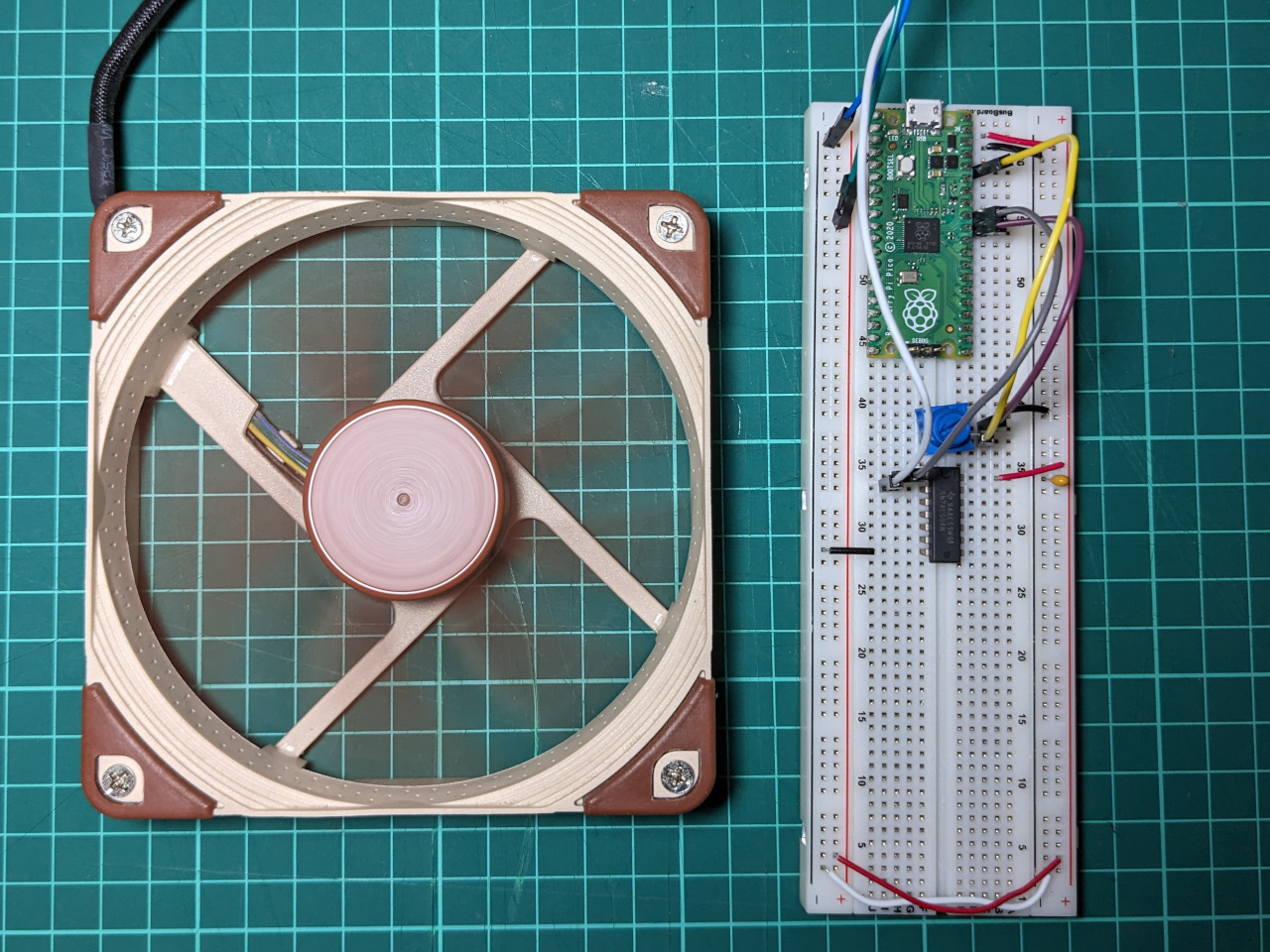
I’m currently working on building a small computer, and want to add some 4-pin computer fans, running quietly at a fixed speed.
This blog post is just a quick set of notes from prototyping, since it covers a few topics which I haven’t written about before.
The problem
The speed of 4-pin computer fans can be controlled by varying the duty cycle on a 25 KHz PWM signal. This signal normally comes from a 4-pin case fan header on the motherboard, which will not be available in this situation. Rather than run the fans at 100%, I’m going to try to generate my own PWM signal.
Two main considerations led me to choose to use a microcontroller for this:
- I’ll need some way to adjust the PWM duty cycle after building the circuit, because I don’t know which value will give the best trade-off between airflow and noise yet.
- Fans need a higher PWM duty cycle to start than they do to run. If I want to run the fans at a very low speed, then I’ll need them to ramp up on start-up, before slowing to the configured value.
It’s worth noting that I’m a complete beginner with microcontrollers. I’ve run some example programs on the Raspberry Pi Pico, but that’s it.
First attempt
I already had MicroPython running on my Raspberry Pi Pico, so that was my starting point.
For a development environment, I installed the MicroPython plugin for PyCharm, since I use JetBrains IDE’s already for programming. Most guides for beginners suggest using Thonny.
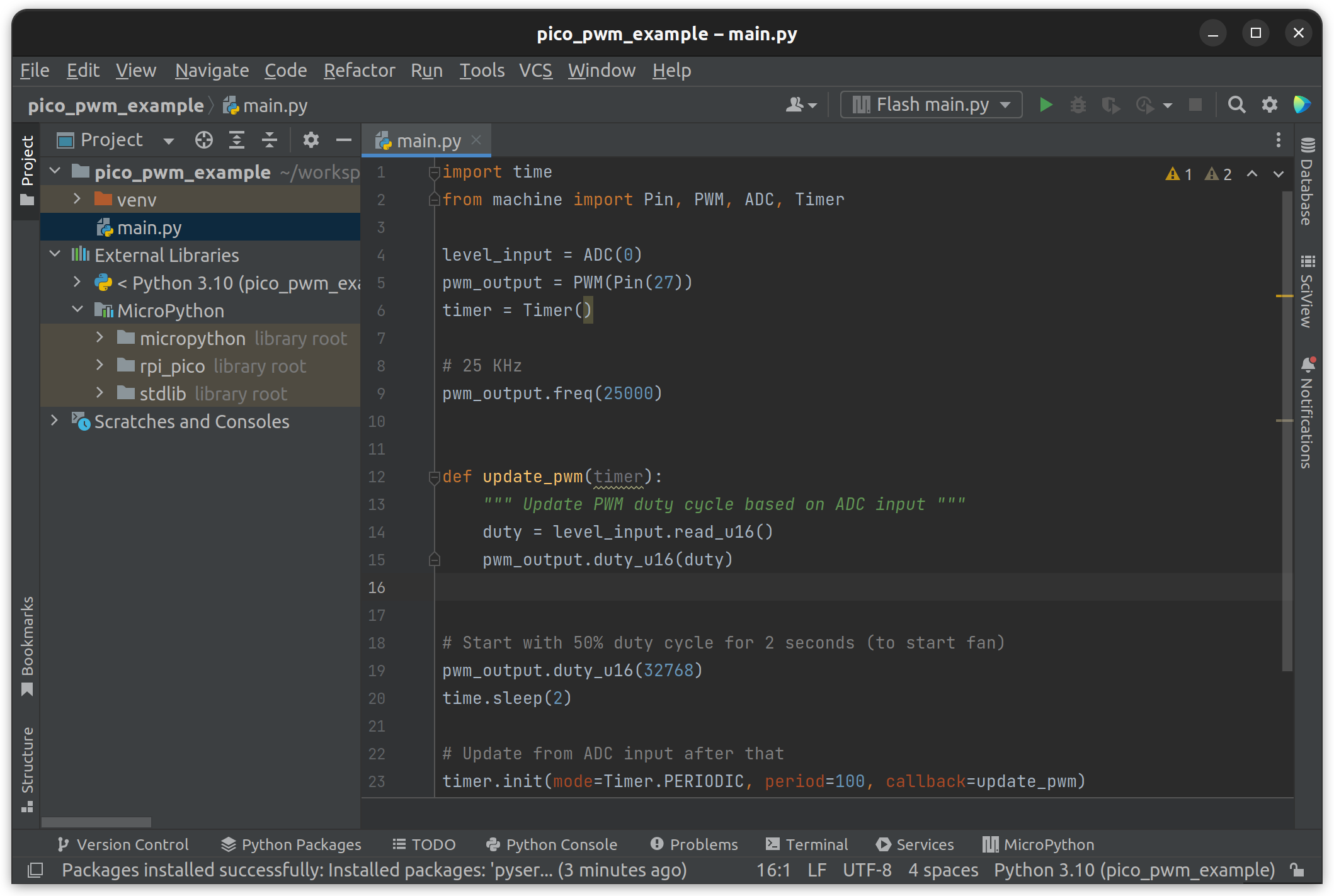
There are introductory examples on GitHub at raspberrypi/pico-micropython-examples which showed me everything I needed to know. I was able to combine an ADC example and a PWM example within a few minutes.
import time
from machine import Pin, PWM, ADC, Timer

level_input = ADC(0)
pwm_output = PWM(Pin(27))
timer = Timer()

# 25 KHz
pwm_output.freq(25000)


def update_pwm(timer):
    """ Update PWM duty cycle based on ADC input """
    duty = level_input.read_u16()
    pwm_output.duty_u16(duty)


# Start with 50% duty cycle for 2 seconds (to start fan)
pwm_output.duty_u16(32768)
time.sleep(2)

# Update from ADC input after that
timer.init(mode=Timer.PERIODIC, period=100, callback=update_pwm)
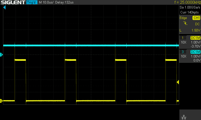
On my oscilloscope, I could confirm that the PWM signal had a 25 KHz frequency, and that the code was adjusting the duty cycle as expected. When the analog input (above) is set to a high value, the PWM signal has a high duty cycle.
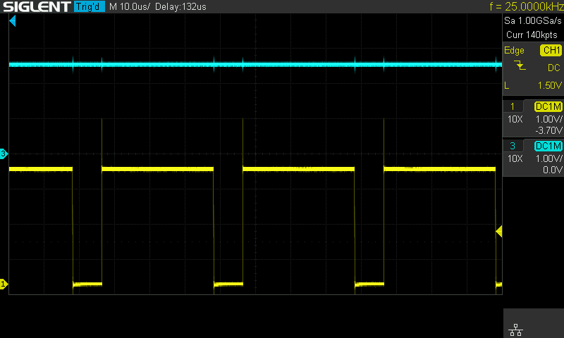
When set to a low value, the PWM signal has a low duty cycle.
But can it control fans?
I wired up a PC fan to 12 V power, and also sent it this PWM signal, but the speed didn’t change. This was expected, since I knew that I would most likely need to convert the 3.3 V signal up to 5 V.
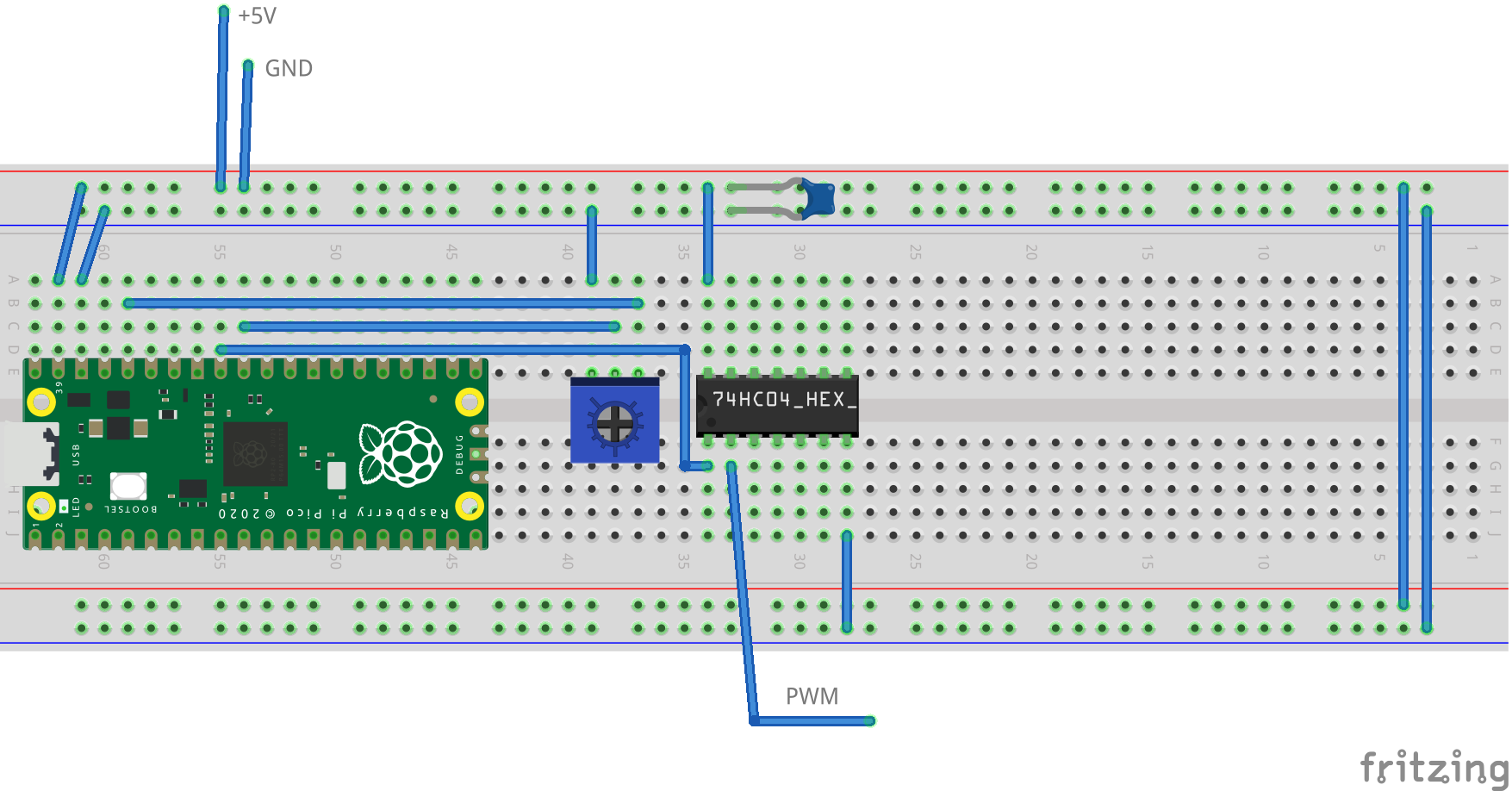
I ran it through a 74LS04 hex inverter with VCC at 5 V, which did the trick. I could then adjust a potentiometer, and the fan would speed up or slow down.
I captured the breadboard setup in Fritzing. Just note that there are floating inputs on the 74LS04 chip (not generally a good idea) and that the part is incorrectly labelled 74HC04, when the actual part I used was a 74LS04.
This shows a working setup, but it’s got more components than I would like. I decided to implement it a second time, on a simpler micro-controller which can work at 5 V directly.
Porting to the ATtiny85
For a second attempt, I tried using an ATtiny85. This uses the AVR architecture (of Arduino fame), which I’ve never looked at before.
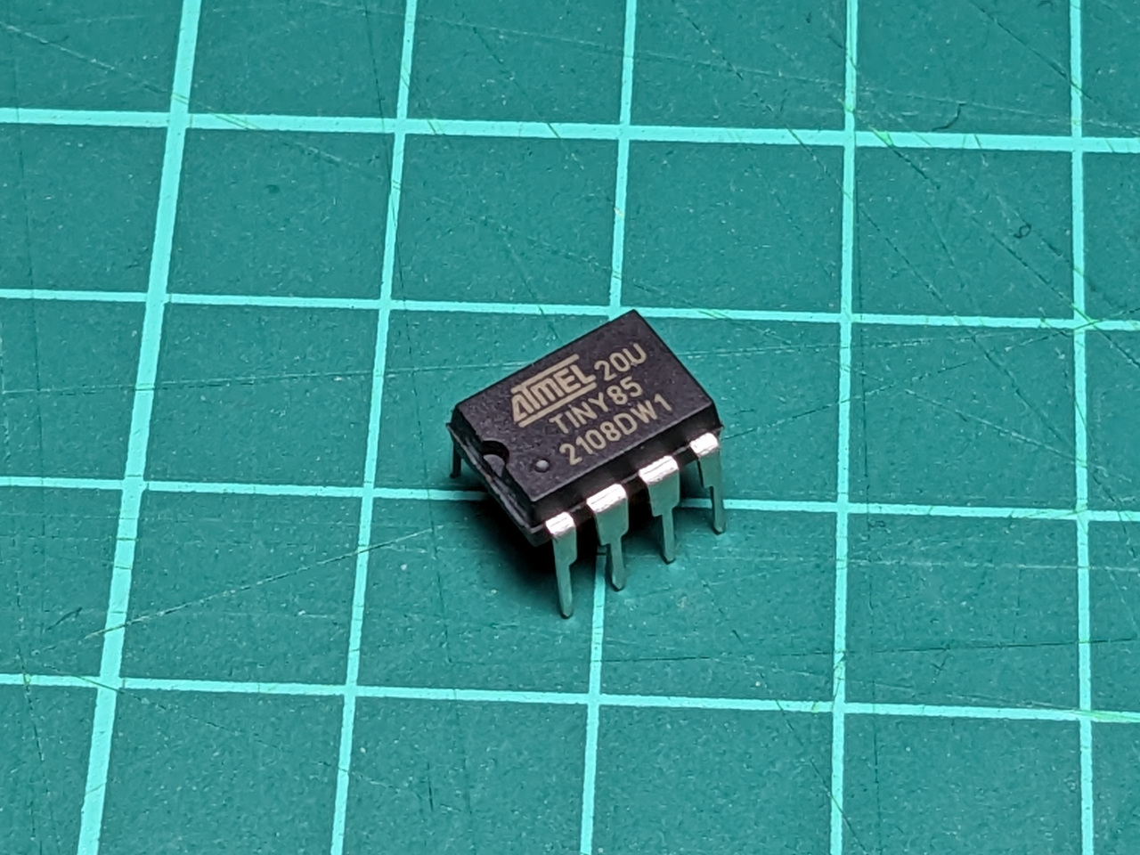
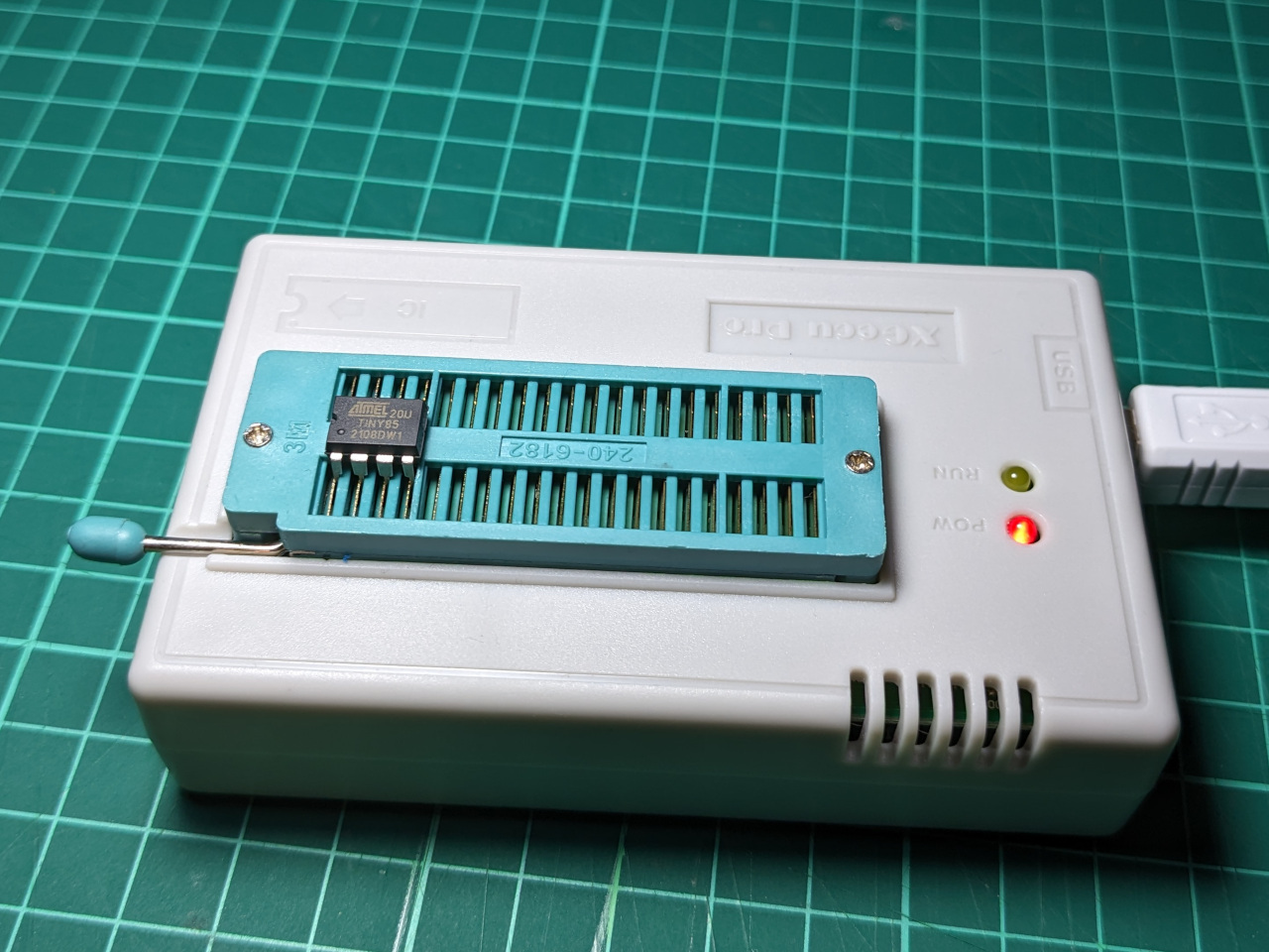
This chip is small, widely available, and can run at 5 V. I can also program it using the TL-866II+ rather than investing into the ecosystem with Arduino development boards or programmers.
I found GPL-licensed code by Marcelo Aquino for controlling 4-wire fans.
After a few false starts trying to compile manually, I followed this guide to get the ATtiny85 ‘board’ definition loaded into the Arduino IDE.
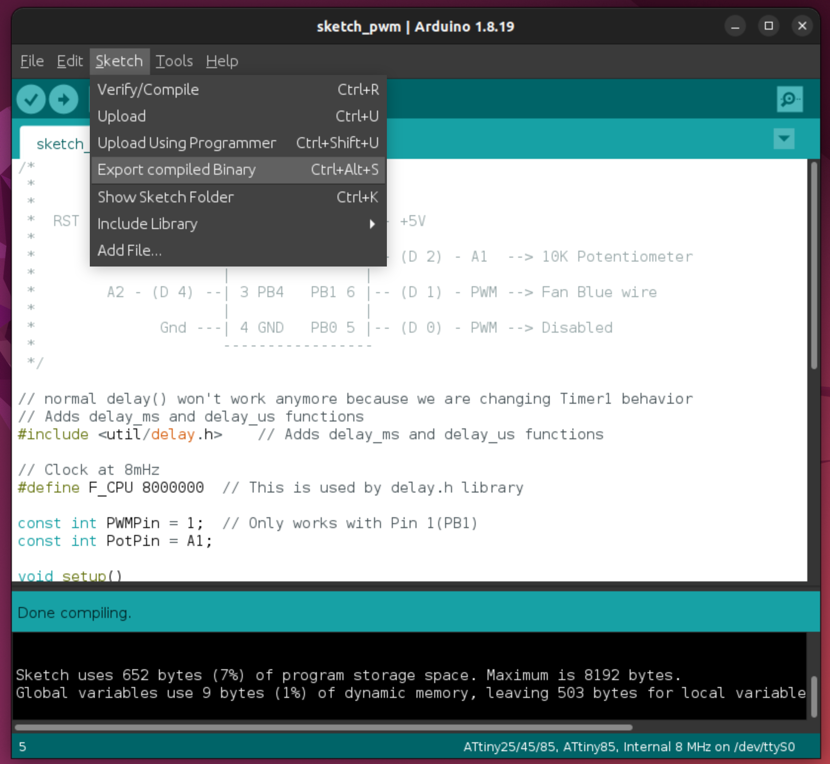
From there I was able to build and get an intel hex file, using the “Export compiled binary” feature.
Writing fuses
The code assumes an 8 MHz clock. The Attiny85 ships from the factory with a “divide by 8” fuse active. This needs to be turned off, otherwise the clock will be 1 MHz. This involves setting some magic values, separate to the program code.
I found these values using a fuse calculator.
The factory default for this chip is:
lfuse 0x62, hfuse 0xdf, efuse 0xff.
To disable the divide-by-8 clock but leave all other values default, this needs to be:
lfuse 0xe2, hfuse 0xdf, efuse 0xff.
I am using the minipro open source tool to program the chip, via a TL-866II+ programmer. First, to get the fuses:
$ minipro -p ATTINY85@DIP8 -r fuses.txt -c config
Found TL866II+ 04.2.126 (0x27e)
Warning: Firmware is out of date.
  Expected  04.2.132 (0x284)
  Found     04.2.126 (0x27e)
Chip ID: 0x1E930B  OK
Reading config... 0.00Sec  OK
This returns the values expected in a text file.
lfuse = 0x62
hfuse = 0xdf
efuse = 0x00
lock = 0xff
I then set lfuse = 0xe2, and wrote the values back with this command.
$ minipro -p ATTINY85@DIP8 -w fuses.txt -c config
Found TL866II+ 04.2.126 (0x27e)
Warning: Firmware is out of date.
  Expected  04.2.132 (0x284)
  Found     04.2.126 (0x27e)
Chip ID: 0x1E930B  OK
Writing fuses... 0.01Sec  OK
Writing lock bits... 0.01Sec  OK
Writing code
Now the microcontroller is ready to accept the exported binary containing the program.
$ minipro -s -p ATTINY85@DIP8 -w sketch_pwm.ino.tiny8.hex -f ihex
Found TL866II+ 04.2.126 (0x27e)
Warning: Firmware is out of date.
  Expected  04.2.132 (0x284)
  Found     04.2.126 (0x27e)
Chip ID: 0x1E930B  OK
Found Intel hex file.
Erasing... 0.01Sec OK
Writing Code...  1.09Sec  OK
Reading Code...  0.45Sec  OK
Verification OK
With the chip fully programmed, I wired it up on a breadboard with 5 V power.
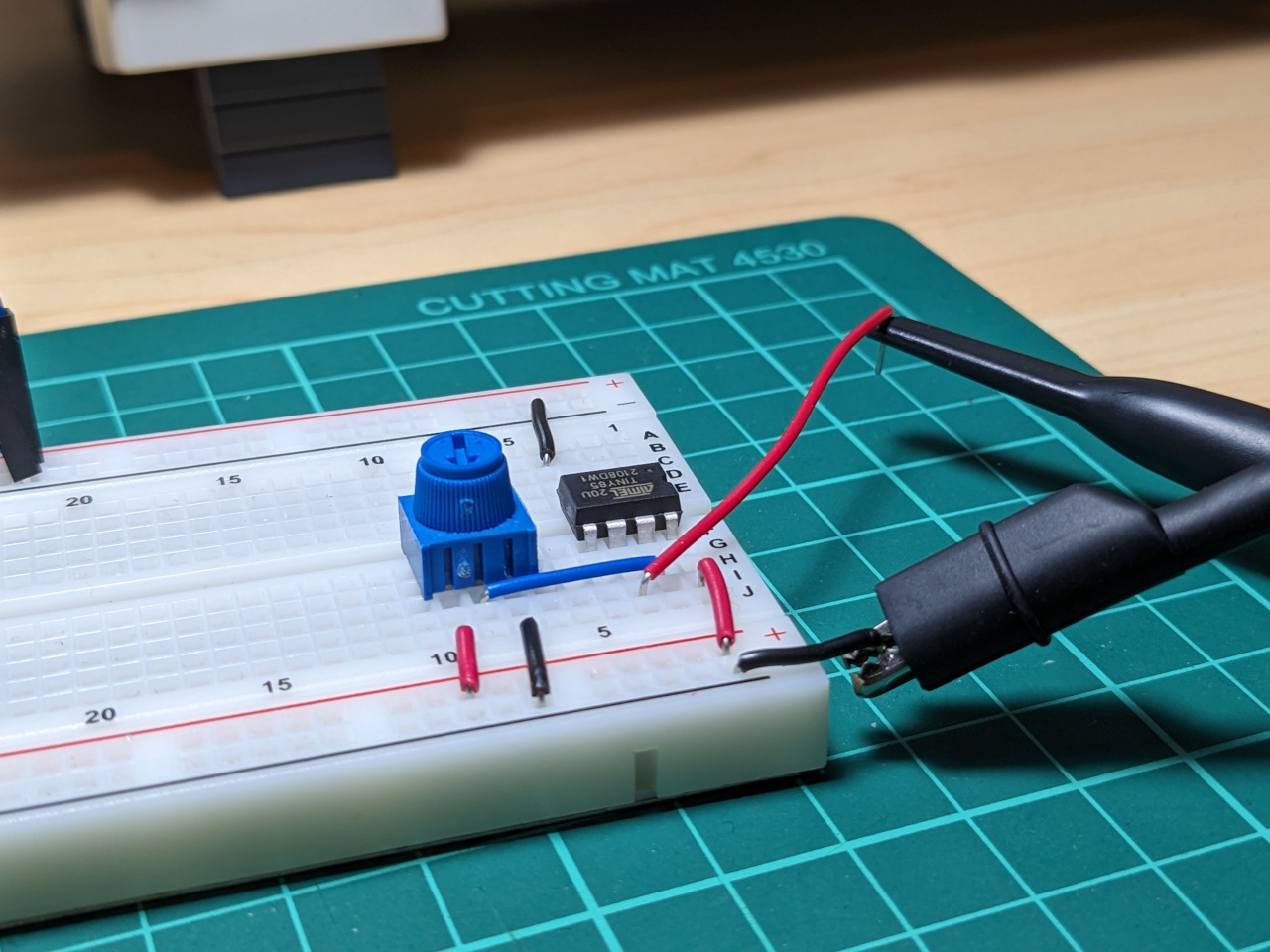
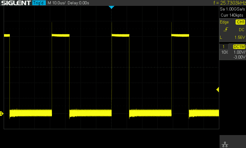
Checking the output again, the signal was the correct amplitude this time, but the frequency does move around a bit. This is likely because I’m using the internal RC timing on the chip, which is not very accurate. My understanding is that anything near 25 KHz will work fine.
Updates
I made only one change to Marcelo’s code, which is to spin the fan at 50% for a few seconds before using the potentiometer-set value. This is to avoid any issues where the fans fail to start because I’ve set them to run at a very low PWM value.
/*
 *                         ATtiny85
 *                      -------u-------
 *  RST - A0 - (D 5) --| 1 PB5   VCC 8 |-- +5V
 *                     |               |
 *        A3 - (D 3) --| 2 PB3   PB2 7 |-- (D 2) - A1  --> 10K Potentiometer
 *                     |               |
 *        A2 - (D 4) --| 3 PB4   PB1 6 |-- (D 1) - PWM --> Fan Blue wire
 *                     |               |
 *              Gnd ---| 4 GND   PB0 5 |-- (D 0) - PWM --> Disabled
 *                     -----------------
 */

// normal delay() won't work anymore because we are changing Timer1 behavior
// Adds delay_ms and delay_us functions
#include <util/delay.h>    // Adds delay_ms and delay_us functions

// Clock at 8mHz
#define F_CPU 8000000  // This is used by delay.h library

const int PWMPin = 1;  // Only works with Pin 1(PB1)
const int PotPin = A1;

void setup()
{
  pinMode(PWMPin, OUTPUT);
  // Phase Correct PWM Mode, no Prescaler
  // PWM on Pin 1(PB1), Pin 0(PB0) disabled
  // 8Mhz / 160 / 2 = 25Khz
  TCCR0A = _BV(COM0B1) | _BV(WGM00);
  TCCR0B = _BV(WGM02) | _BV(CS00);
  // Set TOP and initialize duty cycle to 50%
  OCR0A = 160;  // TOP - DO NOT CHANGE, SETS PWM PULSE RATE
  OCR0B = 80; // duty cycle for Pin 1(PB1)
  // initial bring-up: leave at 50% for 4 seconds
  _delay_ms(4000);
}

void loop()
{
  int in, out;
  // follow potentiometer-set speed from there
  in = analogRead(PotPin);
  out = map(in, 0, 1023, 0, 160);
  OCR0B = out;
  _delay_ms(200);
}
The wiring of the breadboard is shown below. The capacitor is 0.1 µF for decoupling.
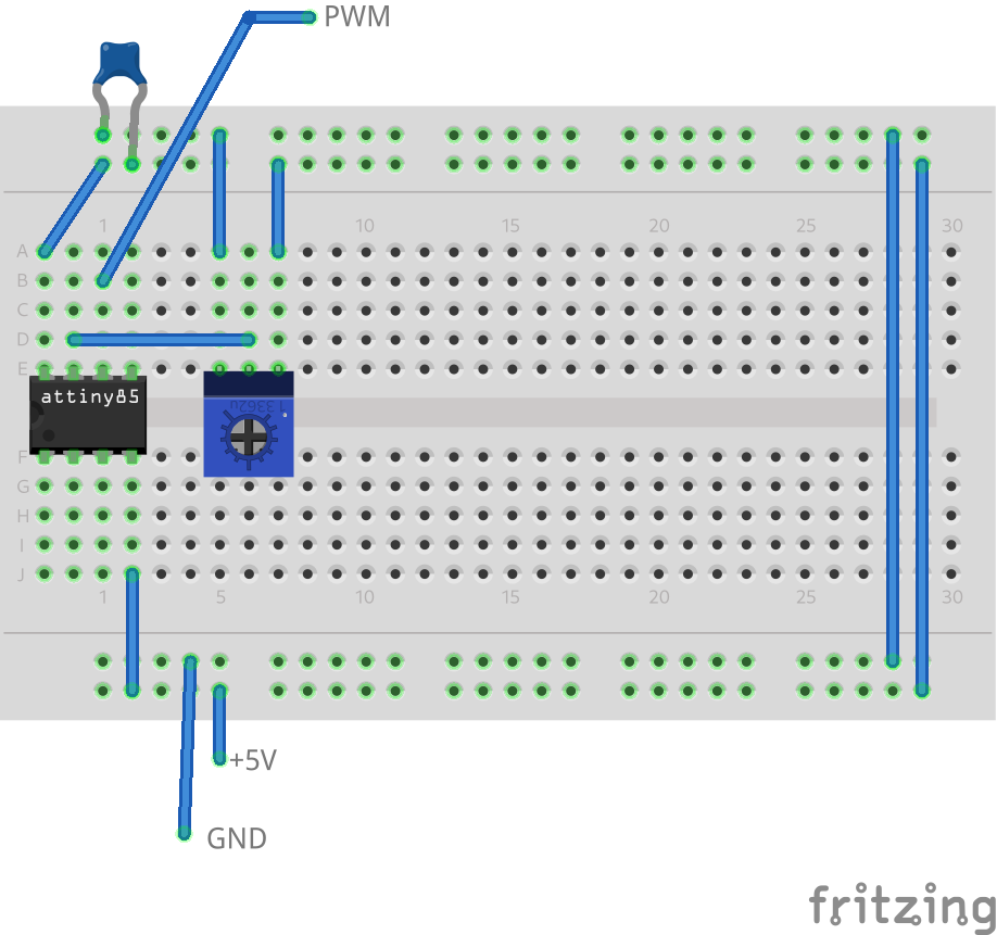
This is far more compact than the Raspberry Pi Pico prototype. I could also miniaturise it further by simply using surface-mount versions of the same components, where using an RP2040 microcontroller from the Pico directly on a custom board would incur some design effort.
Next steps & lessons learned
Although this project is simple, I had to learn quite a few things to prototype it successfully. Using a generic chip programmer like the TL-866II+ appears to be uncommon in the AVR world, and most online guides instead suggest repurposing an Arduino development board or using an Arduino ICSP programmer to program the Attiny85. I was glad to confirm that I could use my existing hardware instead of buying ecosystem-specific items which I would have no other use for. I find the development experience to be far better with the Raspberry Pi Pico, and that’s what I would be choosing for a more complex project.
I also captured the breadboard wiring in Fritzing for this blog post. The diagrams are clearer than a photo of a breadboard, but I’m not confident that they communicate information about the circuit as well as alternative approaches. For future posts, I’ll return to using KiCad EDA for schematic capture, unless there is some reason to highlight the physical layout of a breadboard prototype.
As a next step, I’ll be building a simple break-out PCB for a specific computer case to power the fans and supply a PWM signal, based on the ATtiny85 prototype shown here.