In my previous blog post, I wrote about loading and executing a 512 byte program from an SD card for my 65C816 computer project.
For part 2, I’ll look at what it takes to turn this into a bootloader, which can load a larger program from the SD card. I want the bootloader to control where to read data from, and how much data to load, which will allow me to change the program structure/size without needing to update the code on ROM.
Getting more data
The code in my previous post used software interrupts to print some text to the console, and my first challenge was to implement a similar routine for loading additional data from external storage.
The interface from the bootloader is quite simple: it sets a few registers to specify the source (a block number), destination memory address, and number of blocks to read, then triggers a software interrupt. The current implementation can read up to 64 KiB of data from the SD card each time it is called.
ROM_READ_DISK := $03
; other stuff ...
    ldx #$0000                      ; lower 2 bytes of destination address
    lda #$01                        ; block number
    ldy #$10                        ; number of blocks to read - 8 KiB
    cop ROM_READ_DISK               ; read kernel to RAM
Higher memory addresses
To load data in to higher banks (memory addresses above $ffff, I set the data bank register.
I needed to update a lot of my code to use absolute long (24-bit) addressing for I/O access, where it was previously using absolute (16-bit) addressing, for example:
sta $0c00
In my assembler, ca65, I already use the a: prefix to specify 16-bit addressing. I learned here that I can use the f: prefix for 24-bit addressing.
sta f:$0c00
Without doing this, the assembler chooses the smallest possible address size. This is fine in a 65C02 system, but I find it less helpful on the 65C816, where the meaning of a 16-bit address depends on the data bank register, and the meaning of an 8-bit address depends on the direct page register.
New bootloader
With the ROM code sorted out, I went on to write the new bootloader.
This new code sets the data bank address, then uses a software interrupt to load 8 KiB of data to address $010000
; boot.s: 512-byte bootloader. This utilizes services defined in ROM.
ROM_PRINT_STRING := $02
ROM_READ_DISK := $03

.segment "CODE"
    .a16
    .i16
    jmp code_start

code_start:
    ; load kernel
    ldx #loading_kernel             ; Print loading message (kernel)
    cop ROM_PRINT_STRING
    phb                             ; Save current data bank register
    .a8                             ; Set data bank register to 1
    php
    sep #%00100000
    lda #$01
    pha
    plb
    plp
    .a16
    ldx #$0000                      ; lower 2 bytes of destination address
    lda #$01                        ; block number
    ldy #$10                        ; number of blocks to read - 8 KiB
    cop ROM_READ_DISK               ; read kernel to RAM
    plb                             ; Restore previous data bank register

    ldx #boot                       ; Print boot message
    cop ROM_PRINT_STRING
    jml $010000

loading_kernel: .asciiz "Loading kernel\r\n"
boot: .asciiz "Booting\r\n"

.segment "SIGNATURE"
    wdm $42                         ; Ensure x86 systems don't recognise this as bootable.
The linker configuration for the bootloader is unchanged from part 1.
A placeholder kernel
The bootloader needed some code to load. I don’t have any real operating system to load, so I created the “Hello World” of kernels to work with in the meantime.
This is the simplest possible code I can come up with to test the bootloader. This assembles to 3 machine-language instructions, which occupy just 6 bytes. It is also is position-independent, and will work from any memory bank.
; kernel_tmp.s: A temporary placeholder kernel to test boot process.

ROM_PRINT_CHAR   := $00

.segment "CODE"
    .a16
    .i16
    lda #'z'
    cop ROM_PRINT_CHAR
    stp
The linker configuration for this, kernel_tmp.cfg, creates an 8 KiB binary.
MEMORY {
    ZP:     start = $00,    size = $0100, type = rw, file = "";
    RAM:    start = $0200,  size = $7e00, type = rw, file = "";
    PRG:    start = $e000,  size = $2000, type = ro, file = %O, fill = yes, fillval = $00;
}

SEGMENTS {
    ZEROPAGE: load = ZP,  type = zp;
    BSS:      load = RAM, type = bss;
    CODE:     load = PRG, type = ro,  start = $e000;
}
The commands I used to assemble and link the bootloader are:
ca65 --feature string_escapes --cpu 65816 --debug-info boot.s
ld65 -o boot.bin -C boot.cfg boot.o
The commands I used to assemble and link the placeholder kernel are:
ca65 --feature string_escapes --cpu 65816 --debug-info kernel_tmp.s
ld65 -o kernel_tmp.bin -C kernel_tmp.cfg kernel_tmp.o
I assembled the final disk image by concatenating these files together.
cat bootloader/boot.bin kernel_tmp/kernel_tmp.bin > disk.img
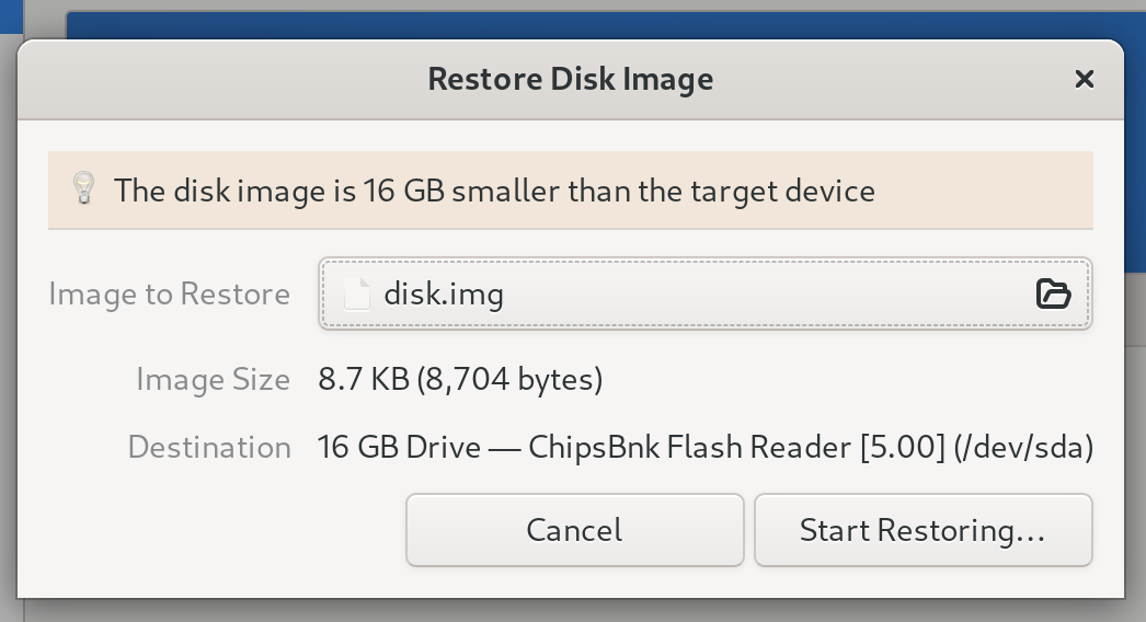
I used the GNOME disk utility to write the image to an SD card, which helpfully reports that I’m not using all of the available space.
Result
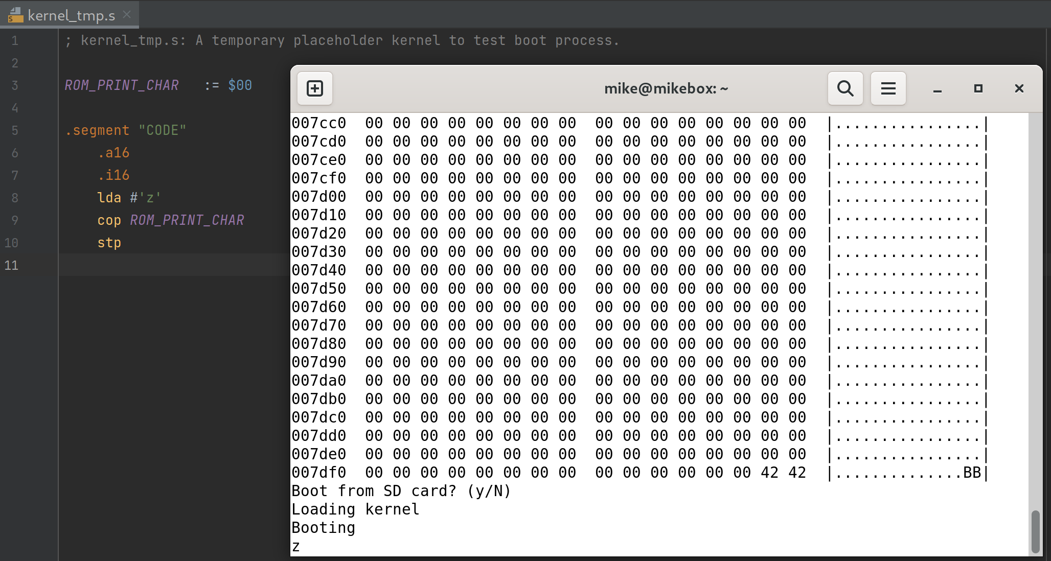
It took me many attempts to get the ROM code right, but this did work. This screen capture shows the test kernel source code on the left, which is being executed at the end of the boot-up process.
If I wanted to load the kernel from within a proper filesystem on the SD card (eg. FAT32), then I would need to update the starting block in the bootloader (hard-coded to 1 at the moment).
The limitations of this mechanism are that the kernel needs to be stored contiguously, be sector-aligned, and located within the first 64 MiB of the SD card.
Speed increase
This was the first time that I wrote code for this system and needed to wait for it to execute. The CPU was clocked at just 921.6 KHz. My SPI/SD card code was also quite generic, and was optimised for ease of debugging rather than execution speed.
I improved this from two angles. My 65C816 test board allows me to use a different clock speed for the CPU and UART chip, so I sped the CPU up to 4 MHz by dropping in an 8 MHz oscillator (it is halved to produce a two-phase clock). As I sped this up, I also needed to add more retries to the SD card initialisation code, since it does not respond immediately on power-up.
I also spent a lot of time hand-optimising the assembly language routine to receive a 512-byte block of data from the SD card. There is room to speed this up further, but it’s fast enough to not be a problem for now.
I had hoped to load an in-memory filesystem (ramdisk) alongside the test kernel, but I’ve deferred this until I can compress it, since reading from SD card is still quite slow.
A debugging detour
Writing bare-metal assembly with no debugger is very rewarding when it works, and very frustrating when there is something I’m not understanding correctly.
I ran into one debugging challenge here which is obvious in hindsight, but I almost couldn’t solve at the time.
This code is (I assure you) a bug-free way to print one hex character, assuming the code is loaded in bank 0. I was using this to hexdump the code I was loading into memory.
.a8                             ; Accumulator is 8-bit
.i16                            ; Index registers are 16-bit
lda #0                          ; A is 0 for example
and #$0f                        ; Take low-nibble only
tax                             ; Transfer to X
lda f:hex_chars, X              ; Load hex char for X
jsr uart_print_char             ; Print hex char for X

hex_chars: .byte '0', '1', '2', '3', '4', '5', '6', '7', '8', '9', 'a', 'b', 'c', 'd', 'e', 'f'
The problem I had was that if the data bank register was 0, this would print ASCII character ‘0’ as expected. But if the data bank register was 1, it would print some binary character.
Nothing in this code should be affected by the data bank register, so I went through a methodical debugging process to try to list and check all of my assumptions. At one point, I even checked that the assembler was producing the correct opcode for this lda addressing mode (there are red herrings on the mailing lists about this).
I was able to narrow down the problem by writing different variations of the code which should all do the same thing, but used different opcodes to get there. This quickly revealed that it was the tax instruction which did not work as I thought, after finding that I could get the code working if I avoided it:
.a8                             ; Accumulator is 8-bit
.i16                            ; Index registers are 16-bit
ldx #0                          ; X is 0 for example
lda f:hex_chars, X              ; Load hex char for X
jsr uart_print_char             ; Print hex char for X

hex_chars: .byte '0', '1', '2', '3', '4', '5', '6', '7', '8', '9', 'a', 'b', 'c', 'd', 'e', 'f'
My first faulty assumption was that if I set the accumulator to 0, then transferring the accumulator value to X would set the X register to 0 as well.
.a8                             ; Accumulator is 8-bit
.i16                            ; Index registers are 16-bit
lda #0                          ; Accumulator is 0
tax                             ; X is 0?
On this architecture, there are two bits of CPU status register which specify the size of the accumulator and index registers. When the accumulator is 8-bits, only the lower 8-bits of the 16-bit value are set by lda. I hadn’t realised that when the index registers are set to 16-bit, the tax instruction transfers all 16 bits of the accumulator to the X register (regardless of the accumulator size), which was causing surprising results.
Far away from the bug-free code I was focusing on, I had used a lazy method to set the data bank register, which involved setting the accumulator to $0101.
My second faulty assumption was that the data bank register was involved at all - in fact lda #$0101 would have been enough to break the later code.
.a16
lda #$0101                      ; Set data bank register to 1
pha
plb
plb
To fix this, when switching to an 8-bit accumulator, I now zero out the high 8-bits.
.a8
lda #0                          ; zero out the B accumulator
xba
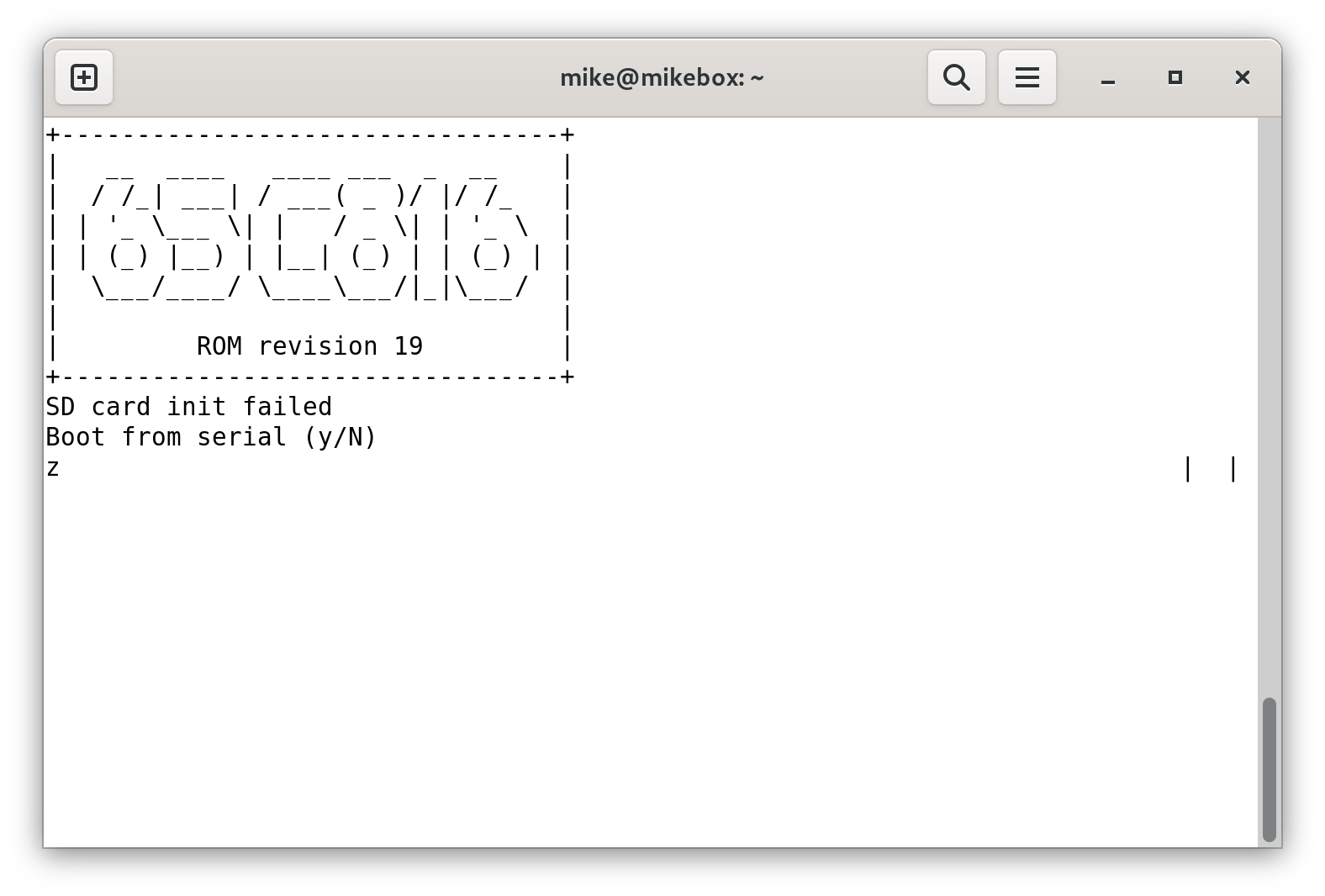
Alternative boot method
I also added an option to boot from serial, based on my implementation of an XMODEM receive function for the 6502 processor.
This is a bit like PXE boot for retro computers. From a program such as minicom, you tell the ROM to boot from serial, then upload the kernel via an XMODEM send. It loads up to 64KiB to bank 1 (the same location as the bootloader on the SD card would place it), then executes it.
This is an important option for testing, since it’s a fast way to get some code running while I don’t have an operating system, and writing to an SD card from a modern computer is not a fast process. It may also be an important fallback if I need to troubleshoot SD card routines.
Wrap-up
Previously, I needed to use a ROM programmer to load code onto this computer. I can now use an SD card or serial connection, and have a stable interface for the bootstrapping code to access some minimal services provided by the ROM.
It is also the first time I’m running code outside of bank 0, breaking through the 64 KiB limit of the classic 6502. There is an entire megabyte of RAM on this test board.
Of course, this computer still does nothing useful, but at least it now controlled by an SD card rather than flashing a ROM. On the hardware side of the project, this will help me to convert the design from 5 V to 3.3 V. I’ll need to convert the ROM to a PLCC-packaged flash chip for that, which is not something I’ll want to be programming frequently.
As far as software goes, my plan is to work on some more interesting demo programs, so that I can start to build a library of open source 65C816 code to work with. The hardware design, software and emulator for this computer can be found on GitHub, at mike42/65816-computer.