I’ve been working on a homebrew computer based on the 16-bit 65C816 CPU. All of my test programs so far have run from an EEPROM chip, which I need to remove and re-program each time I need to make a change.
Plenty of retro systems ran all of their programs from ROM, but I only want to use it for bootstrapping this computer. I’ve got 8 KiB of space for ROM-based programs in the memory map, which should be plenty to check the hardware and load software from disk.
In this two-part blog post, I’ll take a look at handing over control from the ROM to a program loaded from an SD card.
Technical background
I did some quick reading about the process for bootstrapping a PC during the 16-bit era. My homebrew computer is a completely different architecture to an IBM-compatible PC, but I’m planning to follow a few of the conventions from this ecosystem, since I’ll have some similar challenges.
The best resources on this topic are aimed at bootloader developers, such as this wikibooks page.
For a disk to be considered bootable, the first 512-byte sector needs to end with hex 0xAA55 (little-endian) . This is 01010101 10101010 in binary (a great test pattern!). My system is not x68-based, so I’ll store a different value there.
If a disk is bootable, then the BIOS will transfer the 512 byte boot sector to $7C00 and jump to it. The only assumption that the BIOS seems to make about the bootloader structure is that it starts with executable code. I’ll do the same on my system.
It’s worth noting that the first sector may also contain data structures for a filesystem or partitioning scheme, and it’s up to the bootloader code to work around that. For now, my SD card will contain only a bootloader, which does simplify things a bit.
Most bootloaders will then make a series of BIOS calls via software interrupts, which enables them produce text output or load additional data from disk. This is where I’ll have the biggest challenge, since my ROM has no stable interface for a bootloader to call.
Re-visiting SD card handling
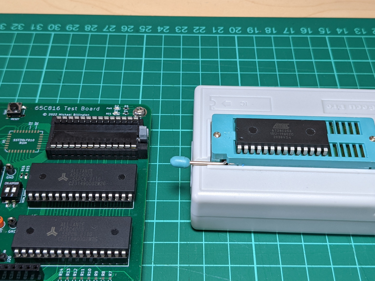
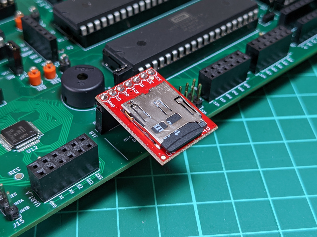
My first task was to load the bootloader itself from SD card, storing the first 512 bytes from the disk to RAM, at address $7C00 onwards. This should be straightforward, since I have working 6502 assembly routines for reading from an SD card, and I’ve added a port for an SD card module to my 65C816 test board.
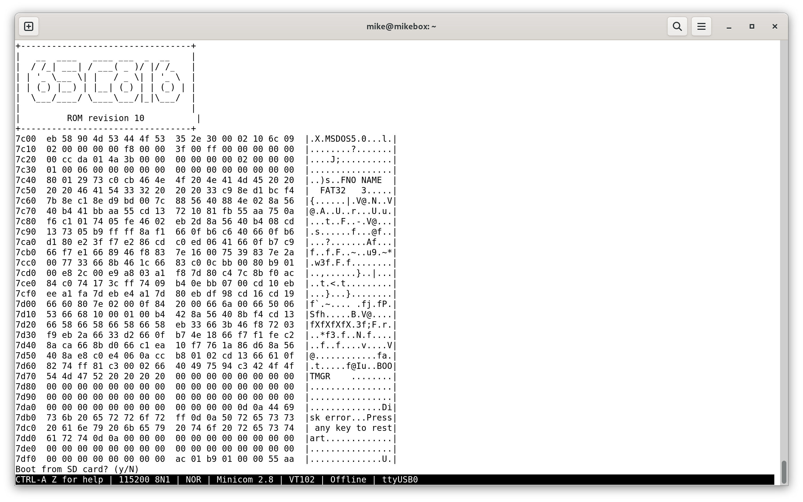
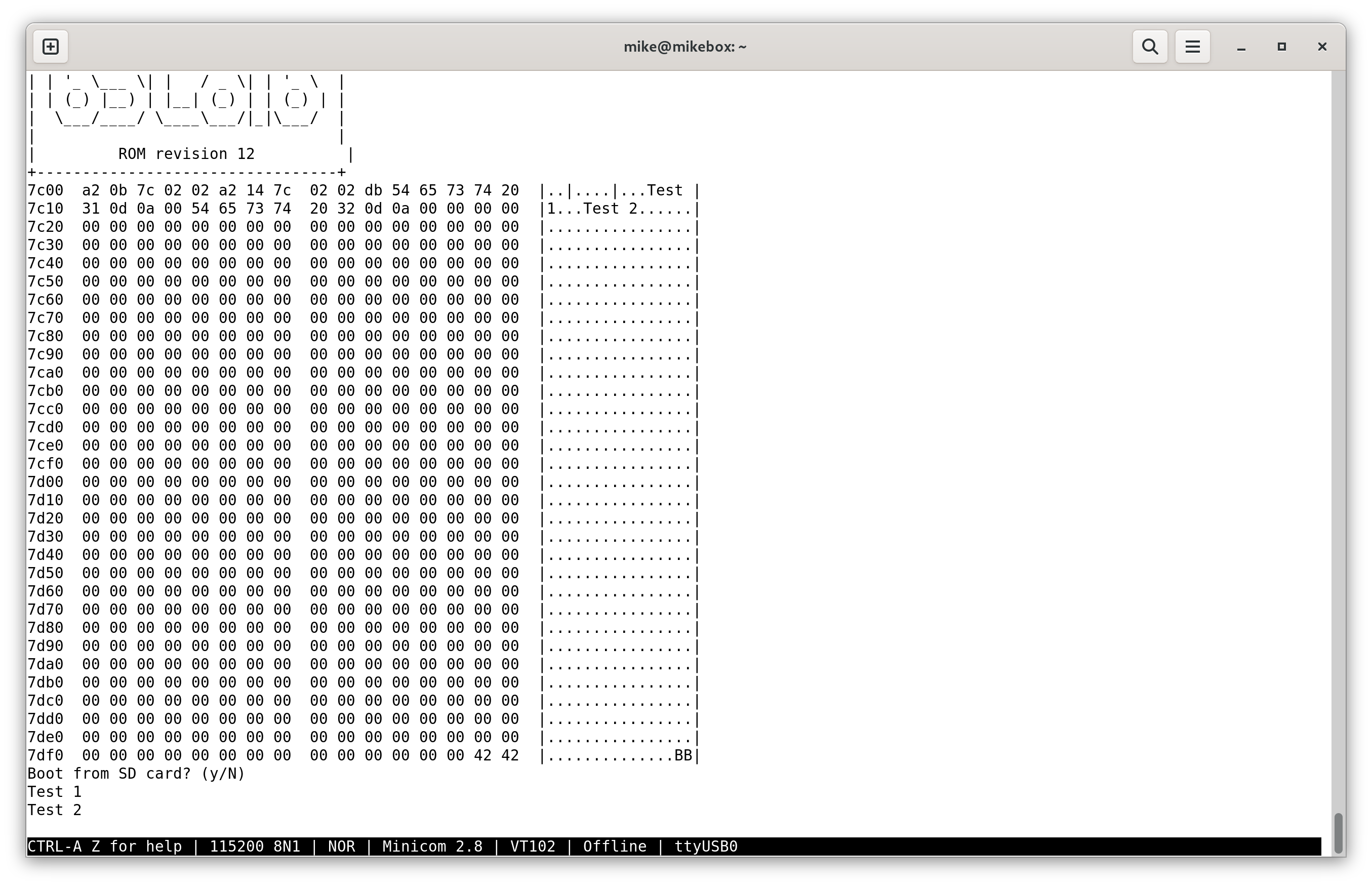
I came up with a routine which prints the contents of the boot sector, then prompts for whether to execute it. My ROM code is not checking the signature at this stage, and is not aware that the boot sector in this screen capture contains x86 machine code within a FAT32 boot sector, but this is a good start.
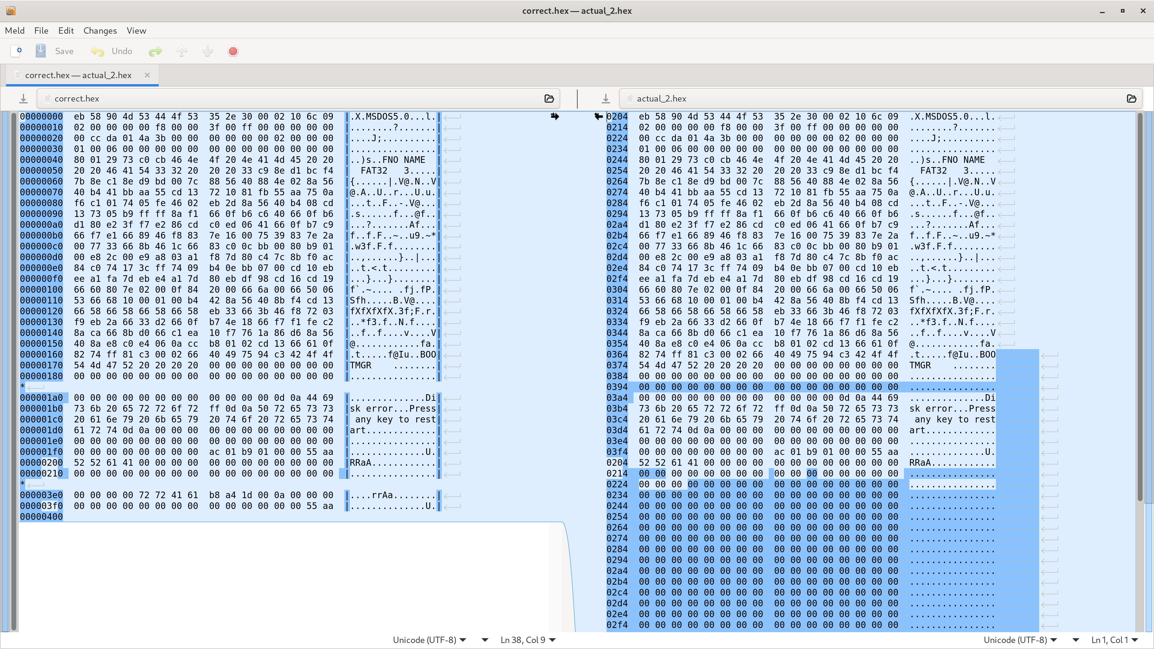
It took quite a few revisions to get this working, since my old 65C02 code for reading from SD produced strange output on this system. On my 65C816 test board, it showed almost the right values, but it was jumbled up, and mixed with SPI fill bytes ($FF). The below screen capture shows a diff between the expected and actual output of the ROM.
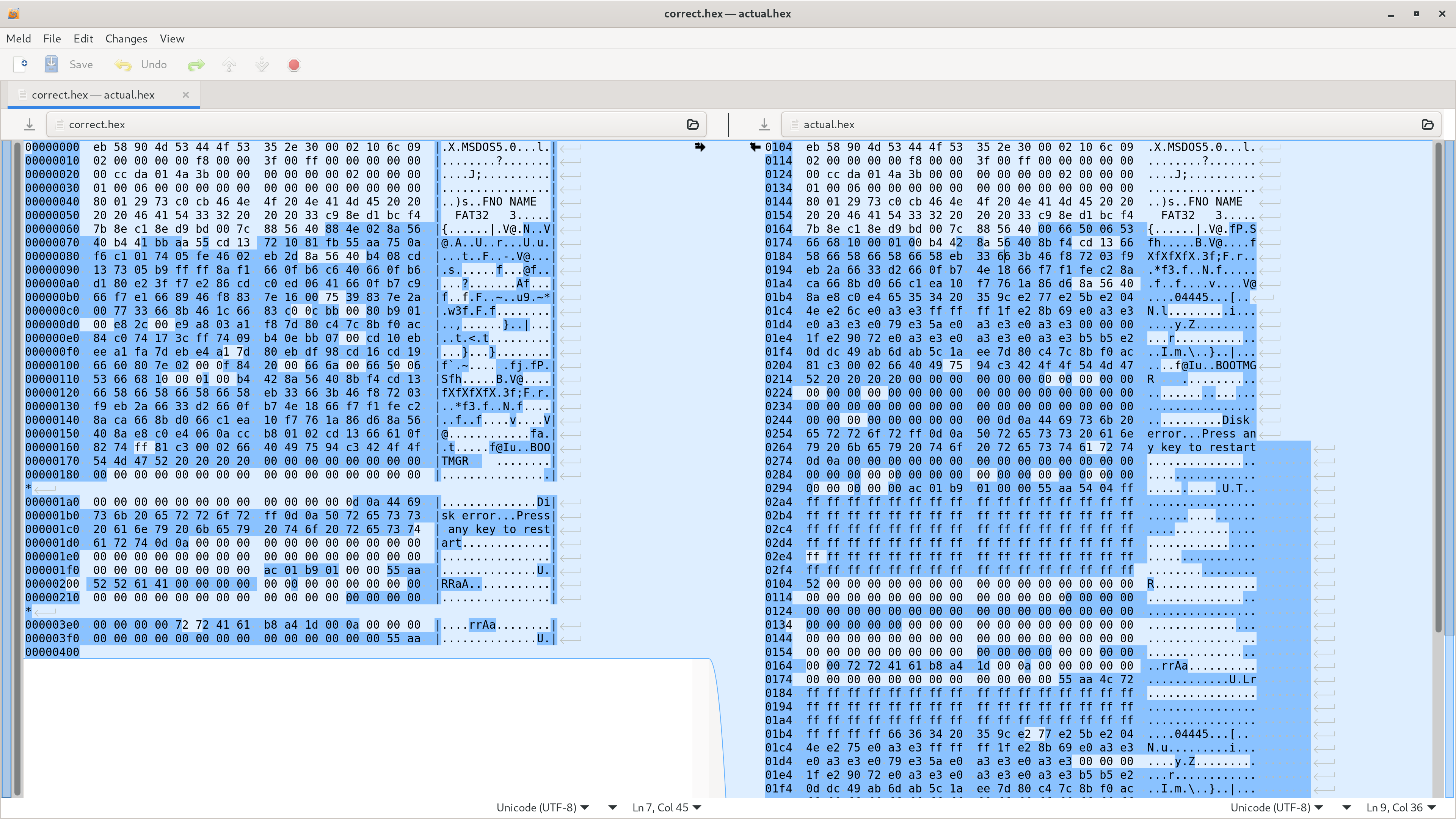
After a long process to rule out other programming and hardware errors, I finally noticed that I was writing the data starting from address $0104, which was never going to work. The default stack pointer on this CPU is $01ff and grows down, so writing 512 bytes to $0104 would always corrupt the stack after a few hundred bytes.
At this stage I was using the assembler to statically allocate a 512 byte space for IO. It appeared in code like this:
.segment "BSS"
io_block_id:              .res 4
io_buffer:                .res 512
The error was in the linker configuration, which I updated to start assigning RAM addresses from $0200 onwards.
 MEMORY {
     ZP:     start = $00,    size = $0100, type = rw, file = "";
-    RAM:    start = $0100,  size = $7e00, type = rw, file = "";
+    RAM:    start = $0200,  size = $7d00, type = rw, file = "";
     PRG:    start = $e000,  size = $2000, type = ro, file = %O, fill = yes, fillval = $00;
 }
The full SD card handling code is too long to post in this blog, but now allows any 512-byte segment from the first 32 MB of the SD card (identified by a 16-bit segment ID) to be loaded into an arbitrary memory address.
Making an API
My next challenge was to define an API for the bootloader to call into the ROM to perform I/O.
I considered using a jump table, but decided to use the cop instruction instead. This triggers a software interrupt on the 65C816, and has parallels to how the int instruction is used to trigger BIOS routines on x86 systems.
I defined a quick API for four basic routines, passing data via registers.
- print char
- read char
- print string
- load data from storage
The caller would need to set some registers, then call cop from assembly language. Any return data would also be passed via registers.
The cop instruction takes a one-byte operand, which in this case specifies the ID of the function to call.
cop $00
To prove that the interface would work, I implemented just the routine for printing strings.
; interrupt.s: Handling of software interrupts, the interface into the ROM for
; software (eg. bootloaders)
;
; Usage: Set registers and use 'cop' to trigger software interrupt.
; Eg:
;   ldx #'a'
;   cop ROM_PRINT_CHAR
; CPU should be in native mode with all registers 16-bit.

.import uart_printz, uart_print_char
.export cop_handler
.export ROM_PRINT_CHAR, ROM_READ_CHAR, ROM_PRINT_STRING, ROM_READ_DISK

; Routines available in ROM via software interrupts.
; Print one ASCII char.
;   A is char to print
ROM_PRINT_CHAR   := $00

; Read one ASCII char.
;   Returns typed character in A register
ROM_READ_CHAR    := $01

; Print a null-terminated ASCII string.
;   X is address of string, use data bank register for addresses outside bank 0.
ROM_PRINT_STRING := $02

; Read data from disk to RAM in 512 byte blocks.
;   X is address to write to, use data bank register for addresses outside bank 0.
;   A is low 2 bytes of block number
;   Y is number of blocks to read
ROM_READ_DISK    := $03

.segment "CODE"
; table of routines
cop_routines:
.word rom_print_char_handler
.word rom_read_char_hanlder
.word rom_print_string_handler
.word rom_read_disk_handler

cop_handler:
    .a16                            ; use 16-bit accumulator and index registers
    .i16
    rep #%00110000
    ; Save caller context to stack
    pha                             ; Push A, X, Y
    phx
    phy
    phb                             ; Push data bank, direct register
    phd
    ; Set up stack frame for COP handler
    tsc                             ; WIP set direct register to equal stack pointer
    sec
    sbc #cop_handler_local_vars_size
    tcs
    phd
    tcd
caller_k := 15
caller_ret := 13
caller_p := 12
caller_a := 10
caller_x := 8
caller_y := 6
caller_b := 5
caller_d := 3
cop_call_addr := 0
    ; set up 24 bit pointer to COP instruction
    ldx <frame_base+caller_ret
    dex
    dex
    stx <frame_base+cop_call_addr
    .a8                             ; Use 8-bit accumulator
    sep #%00100000
    lda <frame_base+caller_k
    sta <frame_base+cop_call_addr+2
    .a16                            ; Revert to 16-bit accumulator
    rep #%00100000

    ; load COP instruction which triggered this interrupt to figure out routine to run
    lda [<frame_base+cop_call_addr]
    xba                             ; interested only in second byte
    and #%00000011                  ; mask down to final two bits (there are only 4 valid functions at the moment)
    asl                             ; multiply by 2 to index into table of routines
    tax
    jsr (cop_routines, X)

    ; Remove stack frame for COP handler
    pld
    tsc
    clc
    adc #cop_handler_local_vars_size
    tcs

    ; Restore caller context from stack, reverse order
    pld                             ; Pull direct register, data bank
    plb
    ply                             ; Pull Y, X, A
    plx
    pla
    rti

cop_handler_local_vars_size := 3
frame_base := 1

rom_print_char_handler:
    ldx #aa
    jsr uart_printz
    rts

rom_read_char_hanlder:
    ldx #bb
    jsr uart_printz
    rts

rom_print_string_handler:
    ; Print string from X register
    ldx <frame_base+caller_x
    jsr uart_printz
    rts

rom_read_disk_handler:
    ldx #cc
    jsr uart_printz
    rts

aa: .asciiz "Not implemented A\r\n"
bb: .asciiz "Not implemented B\r\n"
cc: .asciiz "Not implemented C\r\n"
This snippet is quite dense, and uses several features which are new to the 65C816, not just the cop instruction.
I’m relocating the direct page to use as a stack frame, which is an idea I got from reading the output of the WDC 65C816 C compiler. Pointers are much easier to work with on the direct page.
This is the first snippet I’ve shared which uses a 24-bit pointer, via “direct page, indirect long” addressing. The pointer is used to load the instruction which triggered the interrupt, so that the code can figure out which function to call.
lda [<frame_base+cop_call_addr]
This snippet is also the first time I’ve used the jump to subroutine instruction (jsr) with the “absolute indirect, indexed with X” address mode. On the 65C02, I could only use this addressing mode on the jmp instruction. The only example of that on this blog is also an interrupt handling example.
jsr (cop_routines, X)
The “Hello World” of bootloaders
My next goal was to load a small program from disk, and show that it can call routines from the ROM. For now it is just a program on the boot sector on an SD card, which demonstrates that the new software interrupt API works.
This assembly file boot.s prints out two strings, so that I can be sure that the ROM is returning control back to the bootloader after a software interrupt completes.
ROM_PRINT_STRING := $02

.segment "CODE"
    .a16
    .i16
    ldx #test_string_1
    cop ROM_PRINT_STRING
    ldx #test_string_2
    cop ROM_PRINT_STRING
    stp

test_string_1: .asciiz "Test 1\r\n"
test_string_2: .asciiz "Test 2\r\n"

.segment "SIGNATURE"
    wdm $42                         ; Ensure x86 systems don't recognise this as bootable.
The linker configuration which goes with this is boot.cfg:
MEMORY {
    ZP:     start = $00,    size = $0100, type = rw, file = "";
    RAM:    start = $7e00,  size = $0200, type = rw, file = "";
    PRG:    start = $7c00,  size = $0200, type = rw, file = %O, fill = yes, fillval = $00;
}

SEGMENTS {
    ZEROPAGE:   load = ZP,  type = zp;
    BSS:        load = RAM, type = bss;
    CODE:       load = PRG, type = rw,  start = $7c00;
    SIGNATURE:  load = PRG, type = rw,  start = $7dfe;
}
The commands to assemble and link this are:
ca65 --feature string_escapes --cpu 65816 boot.s
ld65 -o boot.bin -C boot.cfg boot.o
This produces a 512 byte file, which I wrote to SD card.
This is the first time this computer is running code from RAM, which is an important milestone for this project.
Editor improvements
I needed to do some work on my 6502 assembly plugin for IntelliJ during this process, since it didn’t understand the square brackets used for the long address modes.
lda [<frame_base+cop_call_addr]
While I was fixing this, I also implemented an auto-format feature. This saves me the manual effort of lining up all the comments in a column, as is typical in assembly code.
Lastly, I added support for jumping to unnamed labels, which are a ca65-specific feature.
Next steps
In the second half of this blog post, I’ll get the bootloader to load a larger program from the SD card. I’m hoping to allow the bootloader to control how much code to load, and where to load it from.