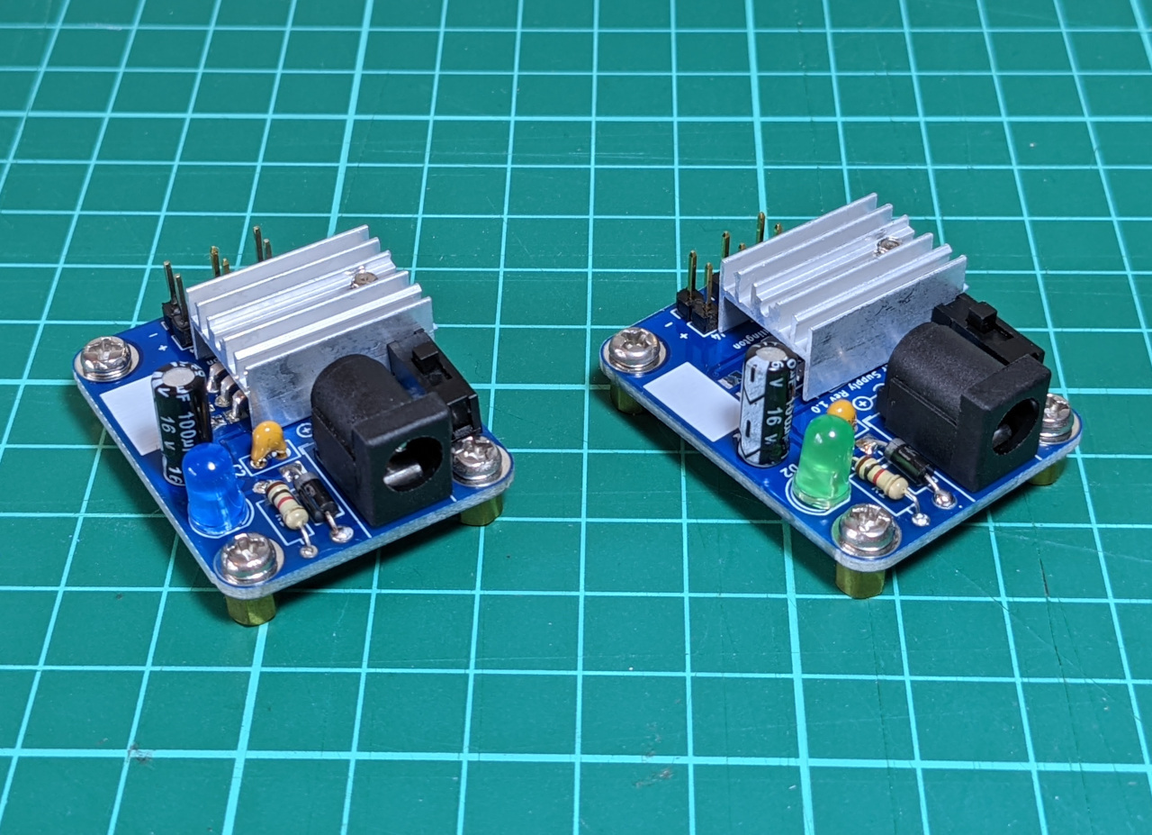
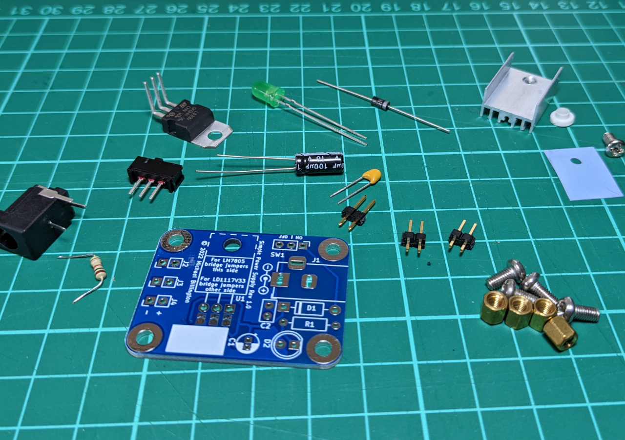
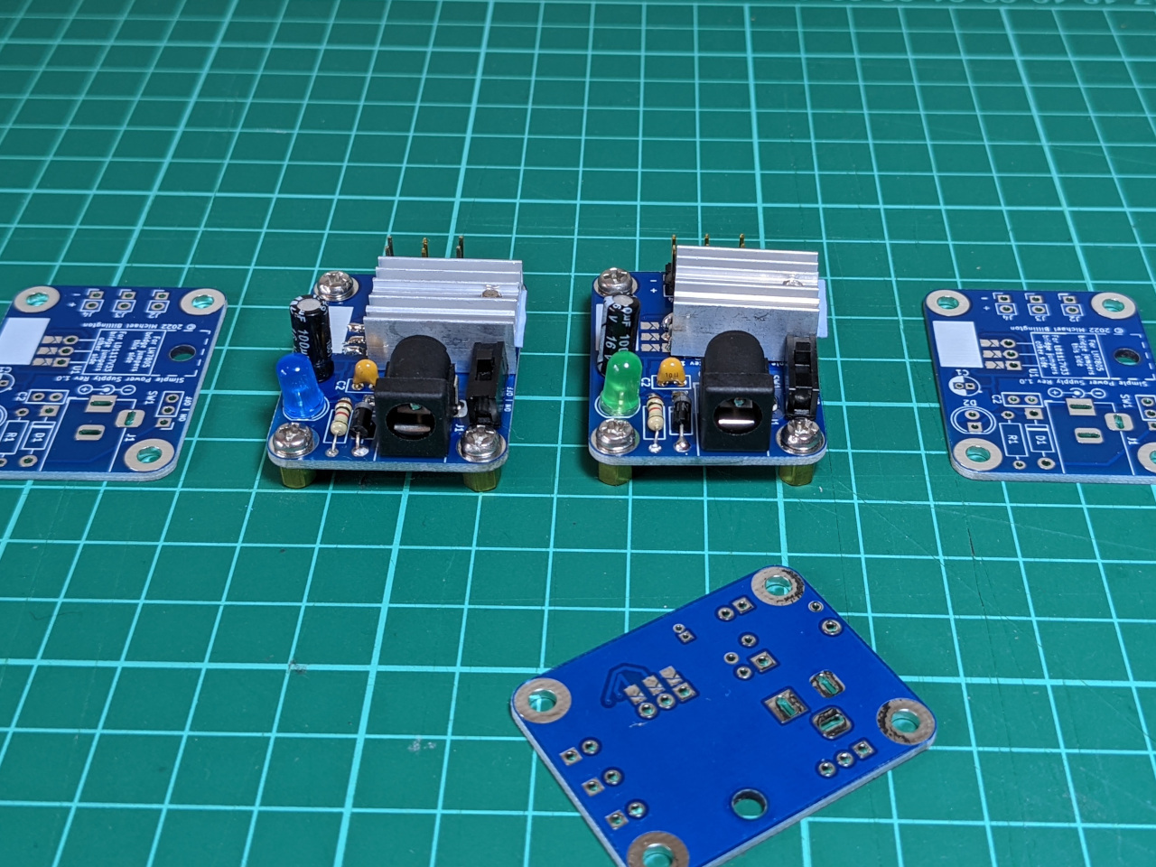
I recently put together a tiny module to power my electronics projects. This is a 3cm x 4cm circuit board, and can be assembled to deliver either a fixed 3.3V or 5V output.
Background: Breadboard power supplies
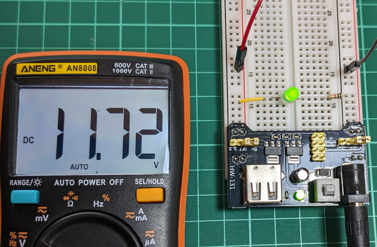
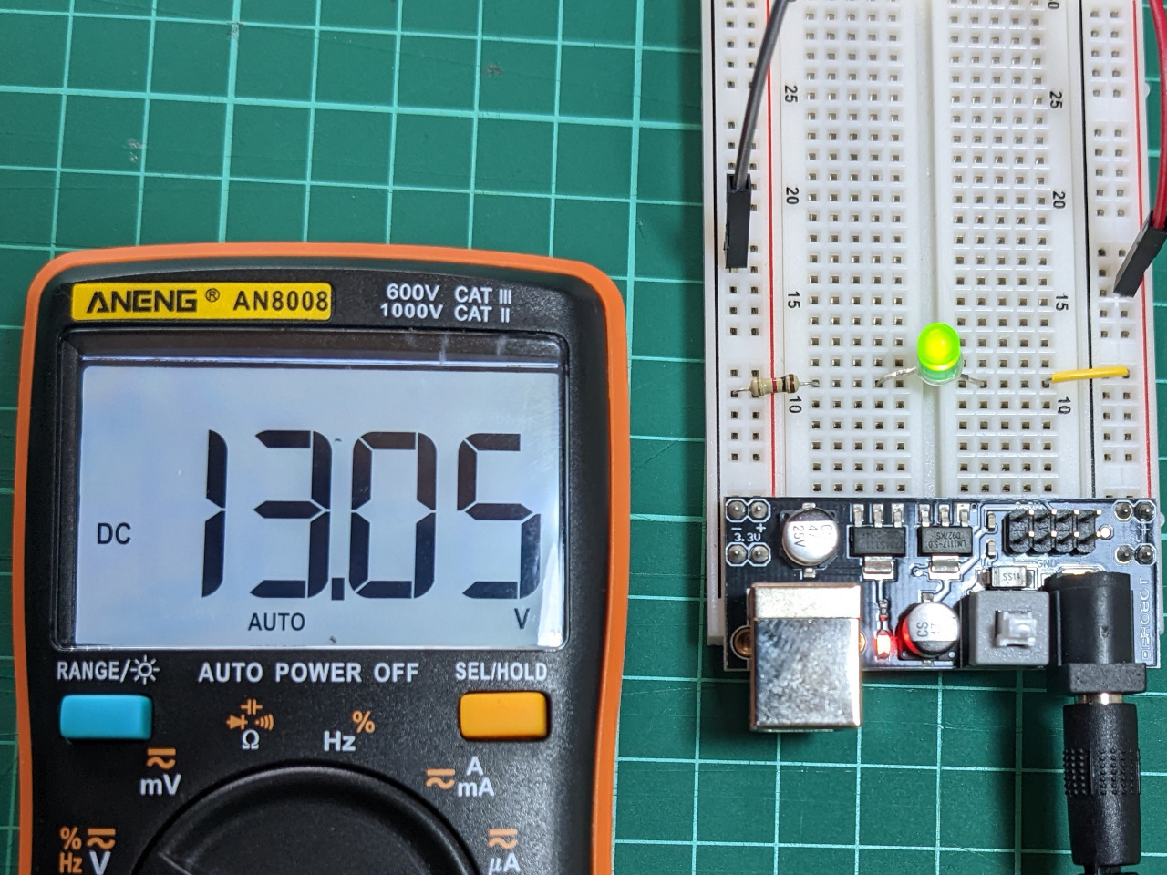
I start a lot of my projects on a breadboard, and previously used a breadboard power supply. The voltage regulators on these are not particularly resilient, and I’ve damaged two of them by wiring something up incorrectly and drawing too much current.
They do not exactly fail-safe, and now pass through the input voltage to whatever I’m working on. This is 12 V in my case, which is enough to fry most of the components I work with.
A bit of searching shows that this is a common issue. The first power supply which did this was a Bud Industries BBP-32701, which uses an LM1117 regulator.
The second one was a DFRobot DFR0140, which uses the AMS1117 regulator.
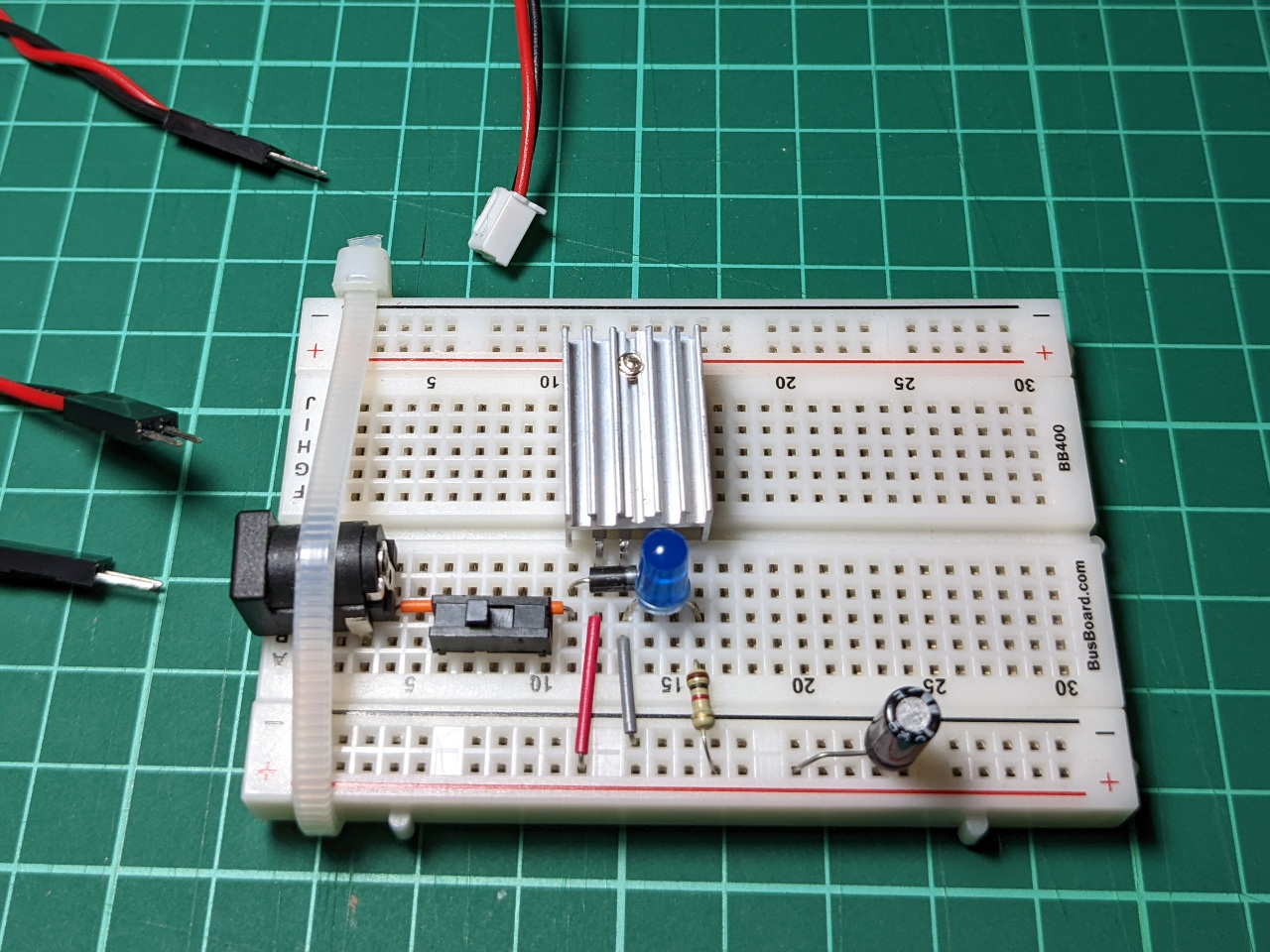
For the past year or so, I’ve used an L7805 regulator connected to a breadboard instead. This is not particularly efficient, but it works well, and I’ve caused enough short circuits to know that the over-current protection works.
Converting to a PCB
My only goal was to take the exact parts I’ve already got, and make them into a more compact module for permanent use.
I used KiCad to capture the schematic and design the board. The minimum order is generally 5 circuit boards, so I planned to assemble some with an L7805 (5 V), and others with a LD33V (3.3 V) regulator. These have different pin-outs, so I added a series of solder jumpers so that I can use the same board for either regulator.

Layout for this PCB was straightforward. It’s a two-layer board, and I added a ground pour on the bottom layer, and the output voltage on most of the top layer.
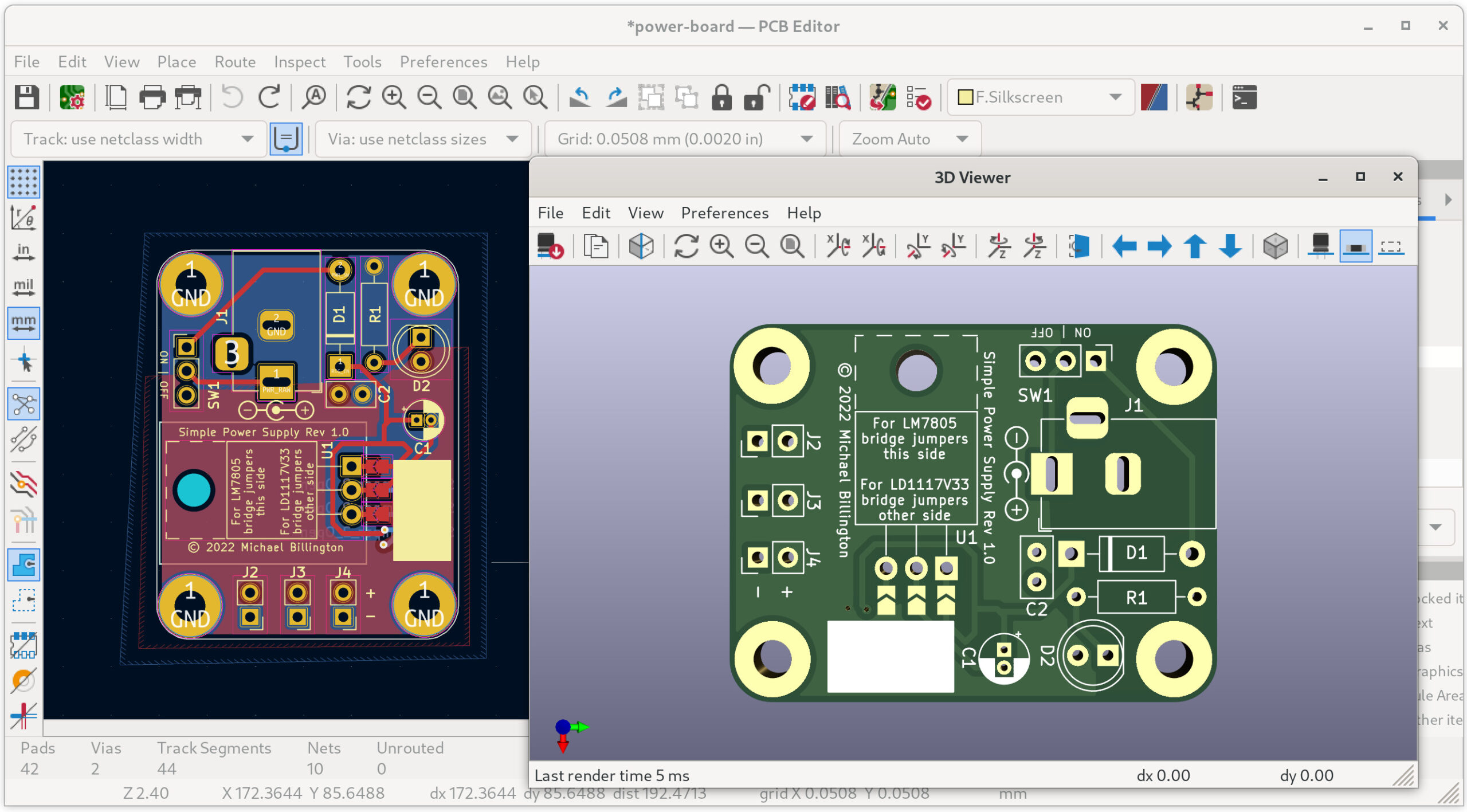
I also decided to switch off thermal relief on the copper pours, to see if a direct connection to a ground plane really makes soldering more difficult (it does! lesson learned).
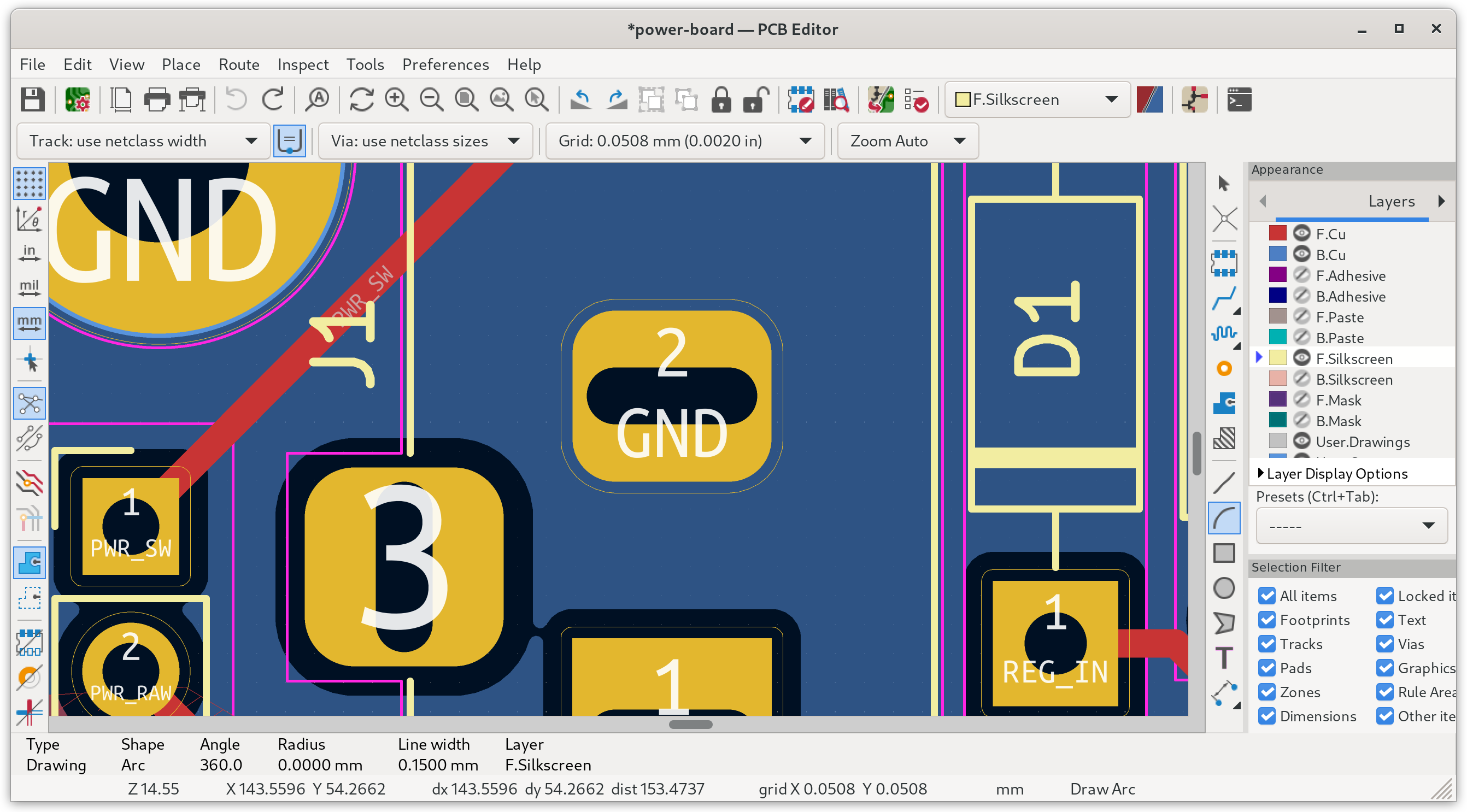
I tried to make this board quite dense, but didn’t go completely overboard: It’s useful to have holes to install standoffs, plus a small area to write on, so that I can distinguish the 5 V and 3.3 V modules later.
Wrap-up
I’m still a little surprised that custom PCB’s are so accessible for hobby use. The unit price of these boards was just 1.36 AUD before shipping, which is cost-competitive with blank prototyping board.
It’s easy to get assembled DC-DC converters, so I don’t suggest building any of these modules yourself. However, as with many of the things I blog about, I’ve uploaded the project files to GitHub under an open source license. The KiCad project, Gerber files and parts list for this project can be found at mike42/simple-power-supply.