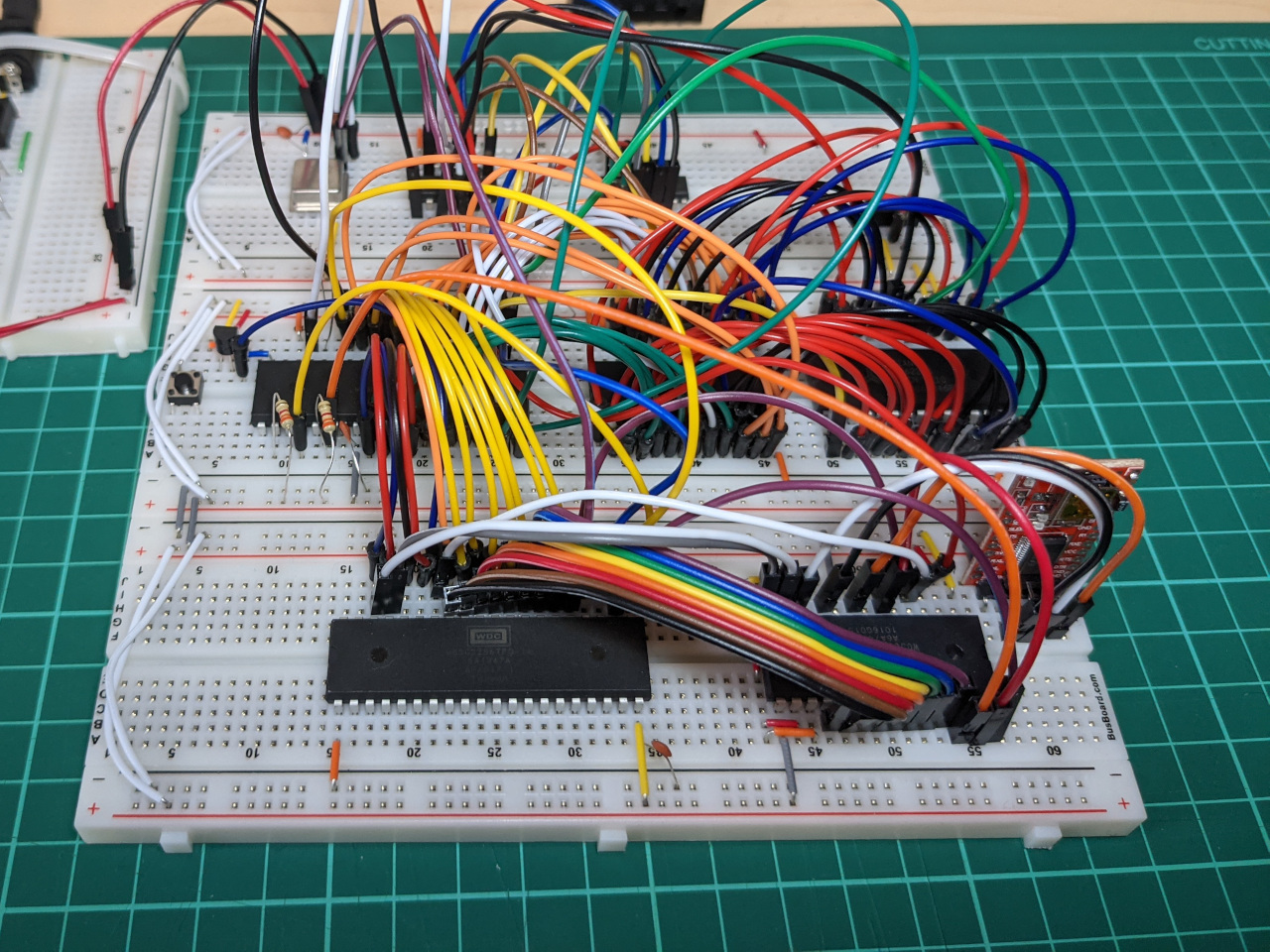
For the past few weeks, I’ve been building a 6502-based retro computer, based originally on a tutorial and design by Ben Eater. My first major change was to add a serial port, so that I can write programs which accept text as input.
This blog post is a list of things which I’ve changed since, to try to make a computer which is a bit more suited to my intended use. My aim at the moment is to lock in a simple base system, so that I can use it as permanent platform for 6502 assembly and hardware experiments.
Re-visiting address decoding
The computer has a 32 KiB RAM chip, and a 32 KiB ROM chip. Due to the way that the glue logic was set up, only 16 KiB of the RAM can be used, but the full ROM space is available.
I wanted to flip this around, since I’m planning to run most programs from RAM, with only a loader or interpreter in the ROM. The idea would be to add a switch to select between the upper and lower half of ROM, map the full RAM in, and leave a large space available for I/O and other experiments.
I planned out a coarse, 2-chip address decoder to achieve this.
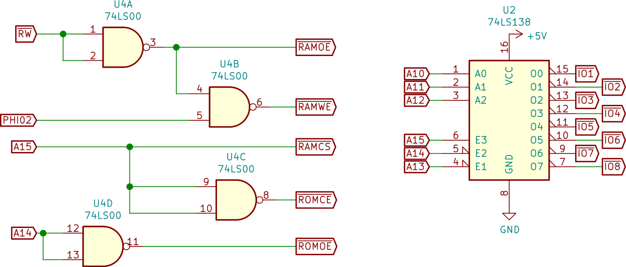
The resulting memory map is:
| Address | Maps to |
|---|---|
| C000-FFFF | ROM - 16 KiB |
| A000-BFFF | Not decoded - 8 KiB |
| 8000-9FFF | I/O - 8 KiB |
| 0000-7FFF | RAM |
This is partly based on the info in Garth Wilson’s address decoding primer, and also Daryl Richtor’s SBC-2 computer.
I re-wired every chip select, modified my test program to use the new memory map, and also added a switch to select between the two halves of the ROM.
Implementing power-on reset
In Ben Eater’s 6502 computer, the reset line is connected to +5v through a resistor, and grounded when a momentary switch is pressed. At power-on, I needed to press the reset button before the computer would do anything useful.
I removed the pull-up resistor from the reset line, and added a DS1813-5+ supervisory IC instead. This holds the reset line low for 150ms at power-on, or when reset is pressed. This suggestion was from the 6502.org forums.
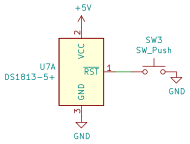
There was no KiCad symbol for the DS1813-5 in the default library, so I needed to create one.
Interrupt lines
I found that I had made an error when connecting the interrupt lines.
The 6502 has two interrupt inputs: IRQ and NMI. On my 6502 computer, the interrupt output of the 65C22S is connected to the IRQ input of the CPU, while the interrupt output of the 65C51S is connected to the NMI input of the CPU.
The 65C51N uses an open-drain IRQ output, so this configuration left the CPU’s NMI input floating most of the time, which caused many spurious interrupts. This was easily fixed by connecting the NMI line to +5v through a 3.3k resistor.
I also implemented some tips from Garth Wilson’s 6502 primer, and connected RDY and BE to +5v through 3.3k resistors, where they had previously been connected to +5v directly.
Power
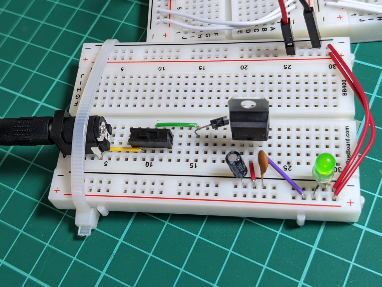
Up until this point, I had been powering my computer with a breadboard power supply. I’m hoping to build something permanent, so I designed a circuit to power it through a DC barrel jack.
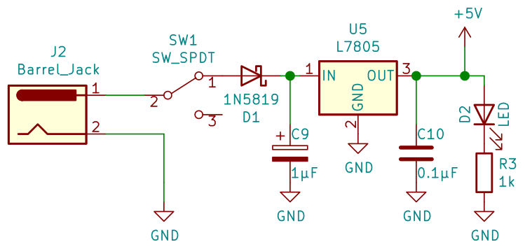
This takes a DC voltage, and steps it down to 5v through a voltage regulator. The other components are a power switch, plus a diode so that I can avoid damaging anything if I connect a plug with the wrong polarity.
This computer does not draw much current, so it’s not necessary to add a heat-sink on the voltage regulator.
Getting my wires crossed
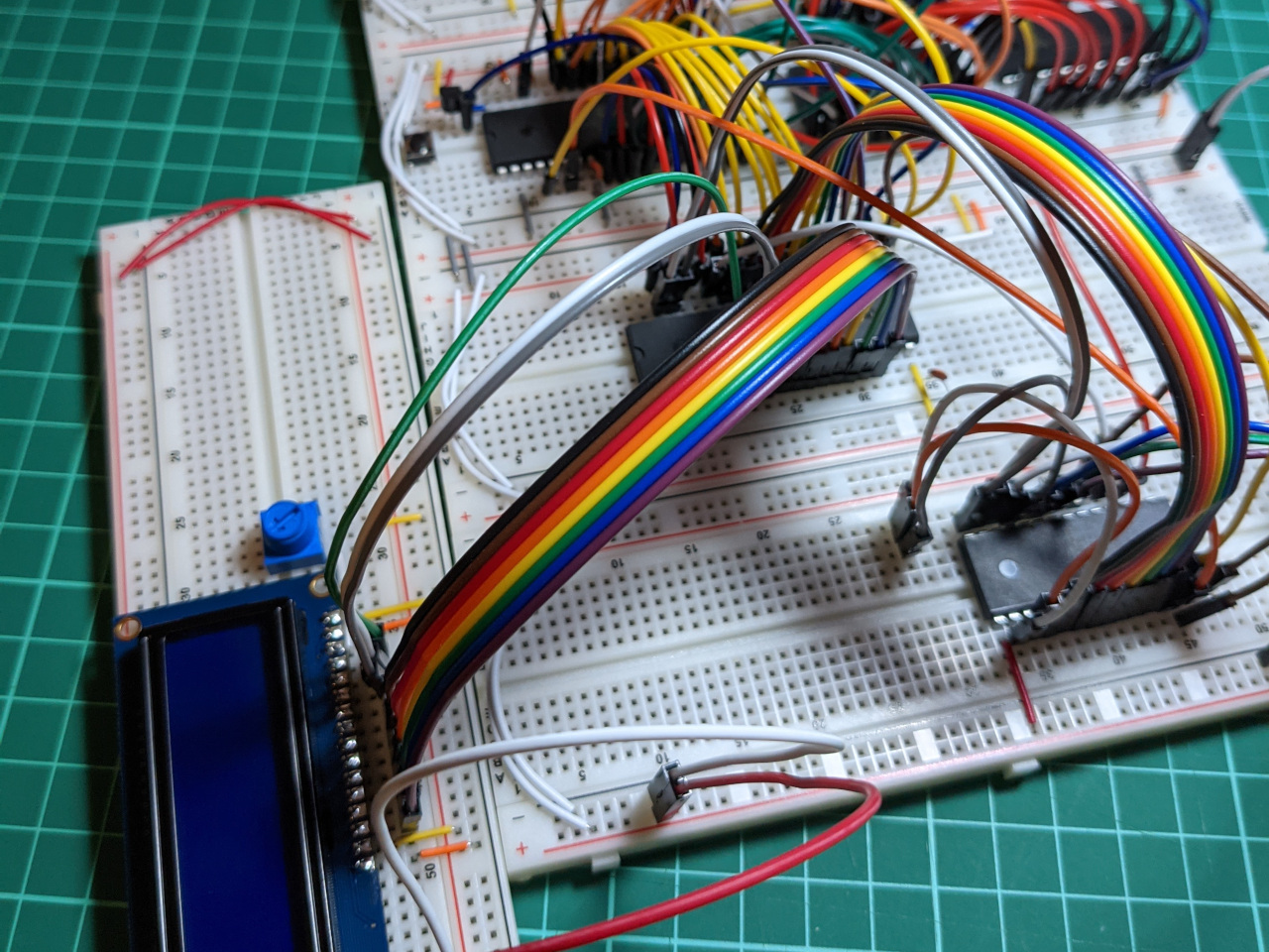
My next change was to remove the LCD screen. This had been useful for debugging, but I would prefer to free up breadboard space and I/O connections for other parts of this project.
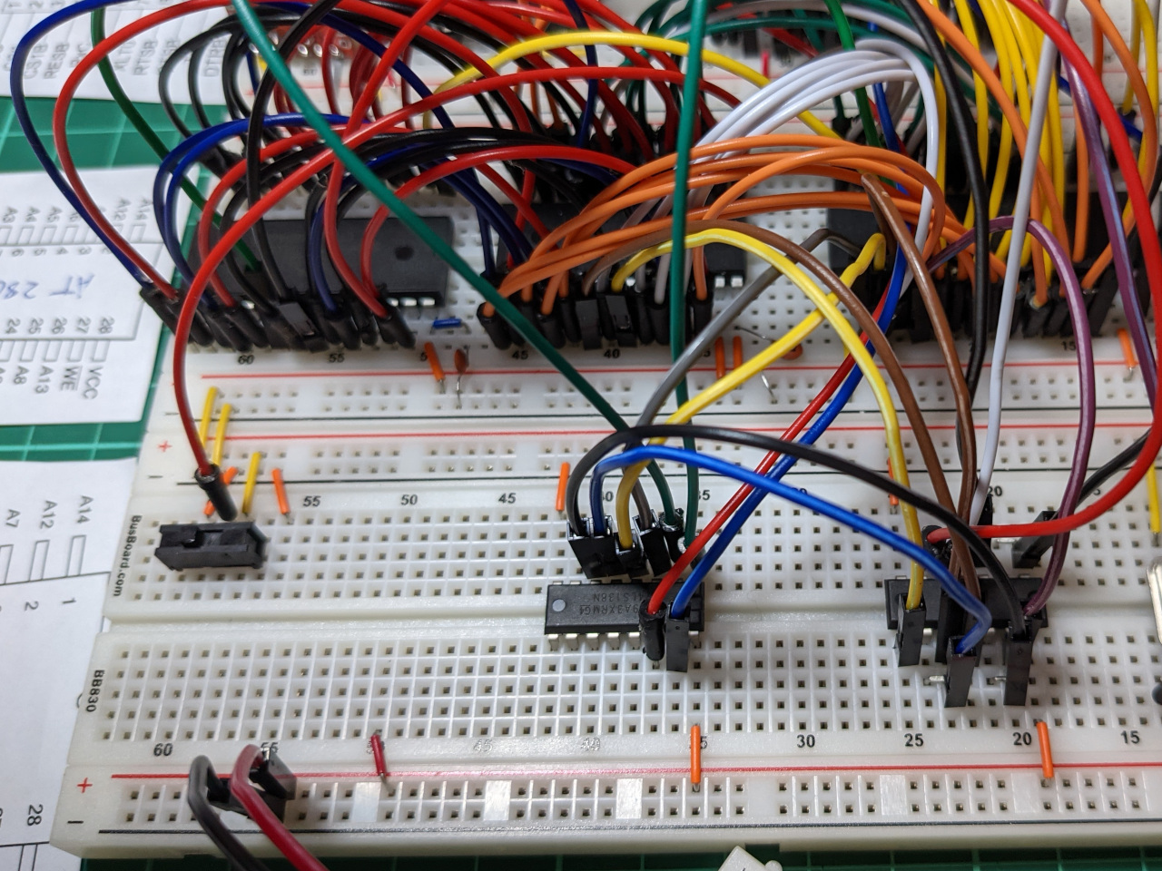
I did this in four steps, testing after each one. First I moved the LCD off to its own breadboard, then updated the computer’s test program to stop using the LCD, ran the computer without the LCD connected, and finally re-located the UART chip into the newly-vacant space.
After the last step, the computer started producing the wrong text (eg. “H” became “D”). I had mixed up two bits in the data bus, and by some luck the UART setup code was not affected. The orange and red wires on the left of this photo are the ones which were swapped.
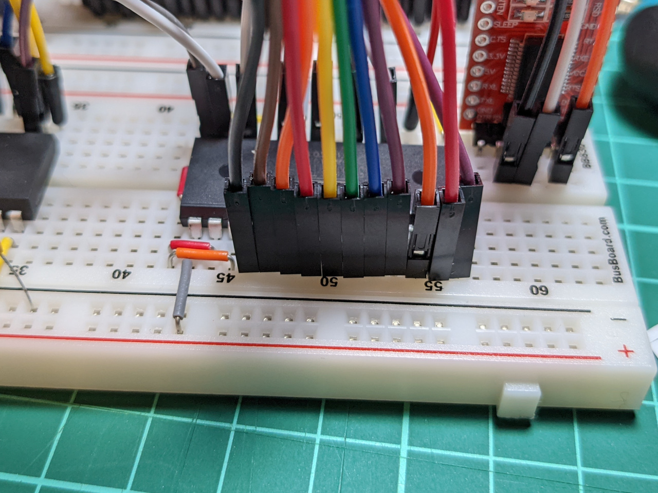
I was able narrow down the source of the problem quickly, since I was breaking everything down into small steps, which were easy to individually verify.
Next steps
For all this effort, not much has changed. I still just have an 8-bit computer which says “Hello” when it starts. The next part of this project will involve porting across some non-trivial software.
On the hardware side, I’ve made a lot of progress learning how to use KiCad. As long as everything works, my plan is to migrate this design from breadboard to a PCB in the near future.