I recently built a compact, quiet rackmount NAS for home. I haven’t seen any builds quite like it online, so I’m writing a bit about how it came together.
The problem
My old backup was a mirrored pair of 2 TB hard drives in an old desktop computer, with a portable 2 TB hard drive as an off-site copy. The disks are now 9 years old, and 2 TB is small enough that I need to ration the space. I also recently repurposed most of the components in that system, so I no longer have an up-to-date backup.
I want to solve this properly, and hopefully build a replacement setup which I can install in my network cabinet, to run 24/7.
But if I’m going to do that, the must-haves are:
- It fits in a 1U rack-mount form-factor with maximum 25cm depth
- It’s quiet
- It has front USB for making an offline copy of the backups
- It has 2 SATA disks - I don’t want to be running a NAS off USB-SATA adapters, for example
- It has wired ethernet - my network is 1 Gigabit
Nice-to-haves would be:
- Fast front USB
- Hot-swap disks or more disks
- Faster network
I’ve worked with servers, and I’ve built small-form-factor computers, so how hard can it be to build a small-form-factor server?
Parts list
I spent a lot of time sketching out possible builds in LibreOffice Draw. Every combination of parts had some compromise, which is a familiar theme from small-form-factor PC building.
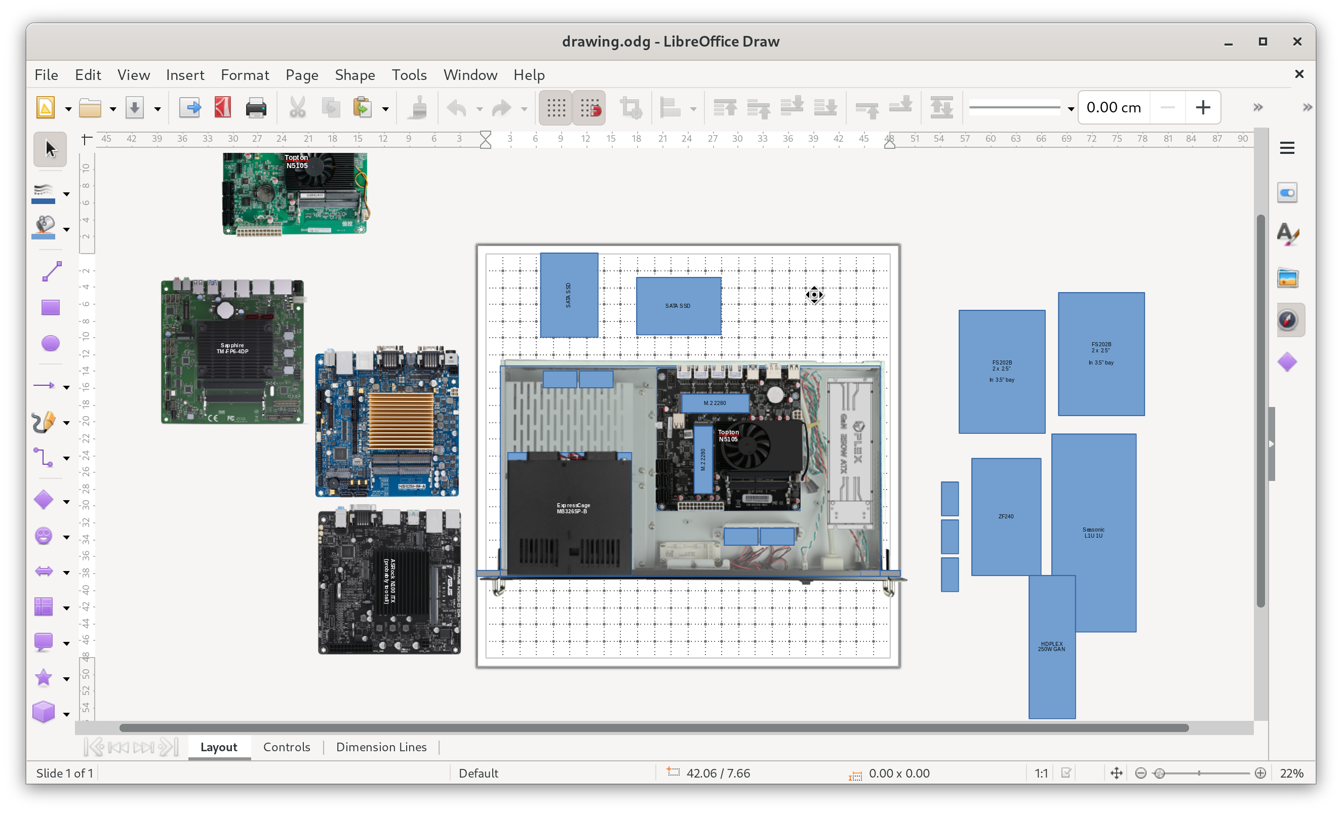
I ended up deciding on parts which follow normal PC standards, hopefully giving me a good chance of keeping it working for many years.
- Case: Case Athena Power RM1UC138
- Power supply: HDPLEX GAN 250W
- Motherboard: Topton N6005 Mini ITX
- RAM: Crucial 16GB (2 x 8GB) DDR4 3200 SO-DIMM
- Boot disk: Samsung 970 EVO Plus 1TB M.2 SSD
- Storage disks: 2 x Samsung 870 QVO 8TiB 2.5" SSD
- Fans: 4 x Noctua A4x20 PWM
- Drive cage: Icy Dock MB608SP-B - 6 x 2.5" SATA bays
- Set of 6 x 50cm SATA cables
There are some compatibility issues in the above part list, and it took a little bit of problem-solving to get everything working together.
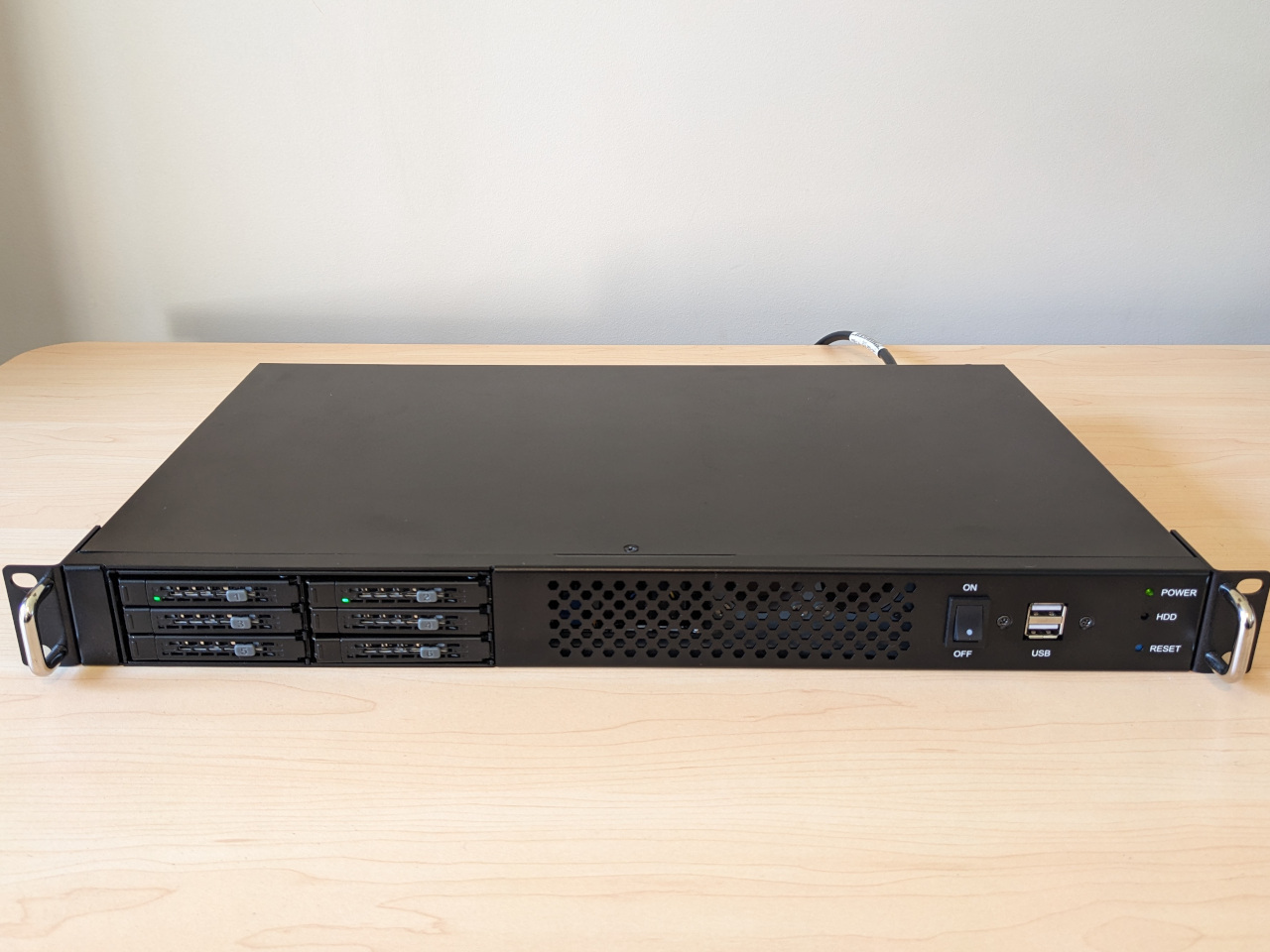
Closer look at the Athena Power RM1UC138
Short-depth 1U computer cases are nearly impossible to find in Australia. I ordered the Athena Power RM1UC138 from the United States, which is an OEM case with some flexibility built in.
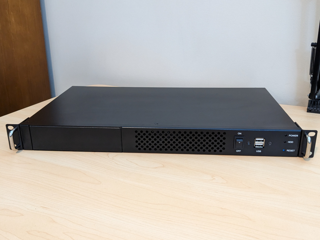
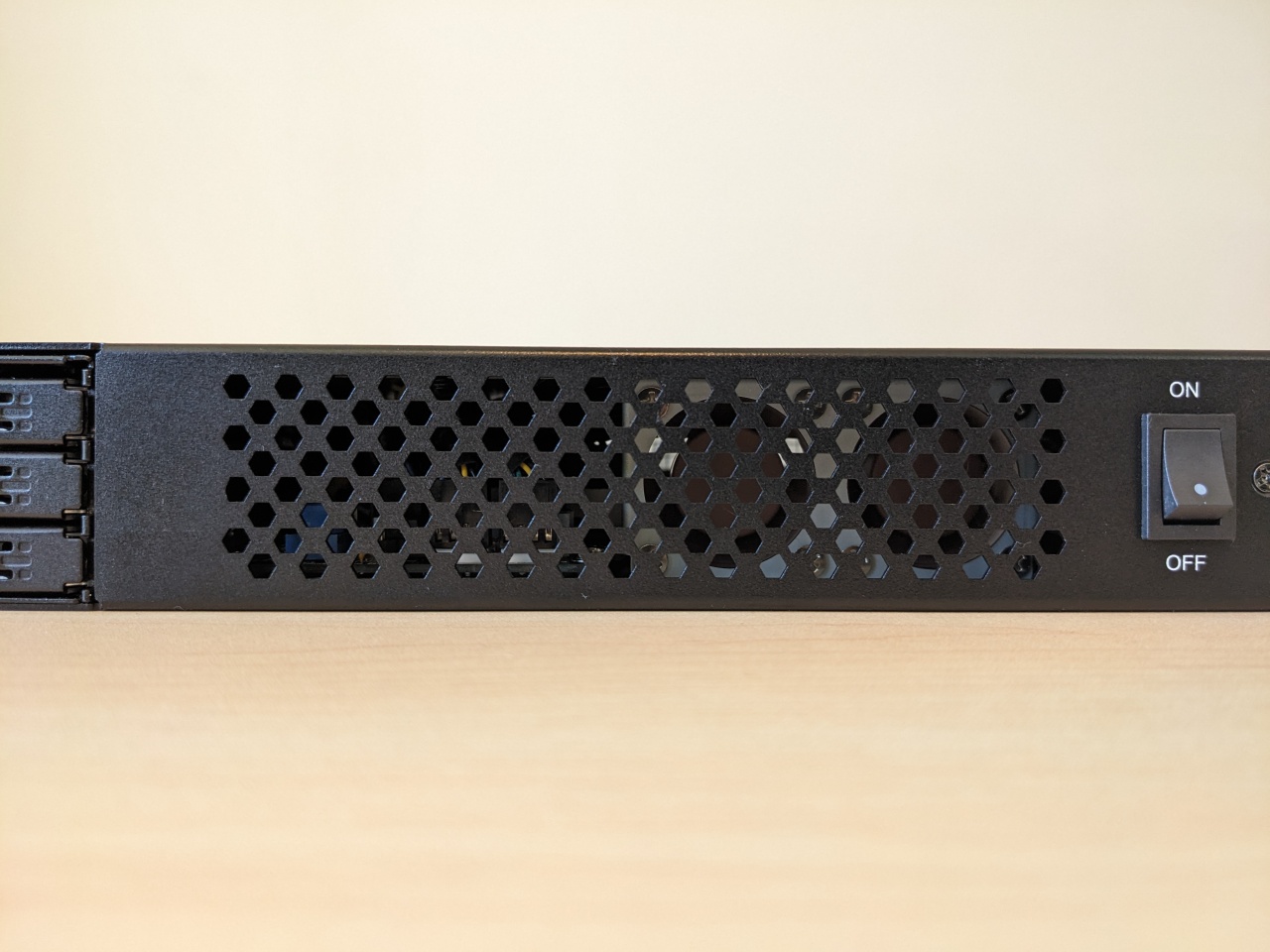
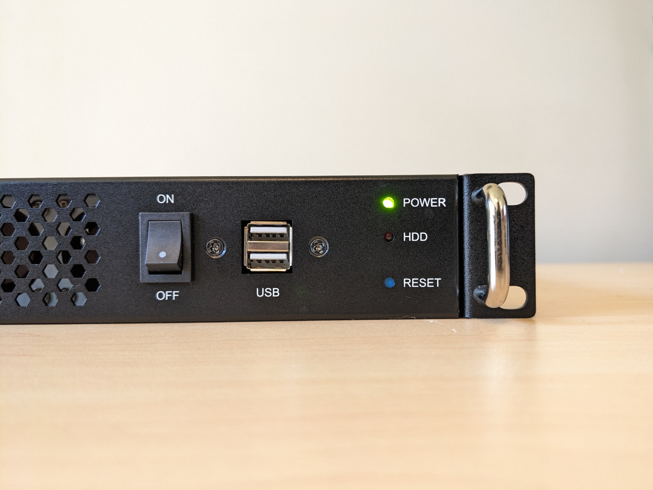
On the front it has a 5.25" bay, which I plan to use to add a drive cage. The front USB is only USB 2.0, which would normally be a disadvantage, but in this instance is a good match for the motherboard I’m using. The power button looks like a toggle switch, but is actually a momentary switch.
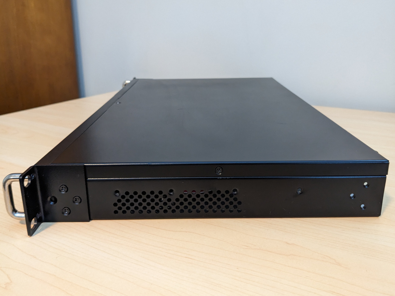
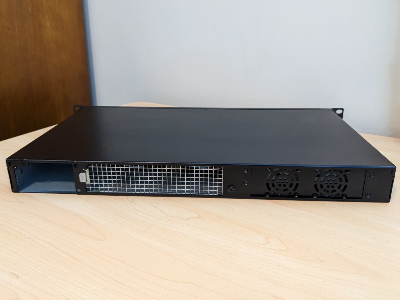
The side shows that the rack ears can be put on the front or back, allowing the case to be mounted in either direction.
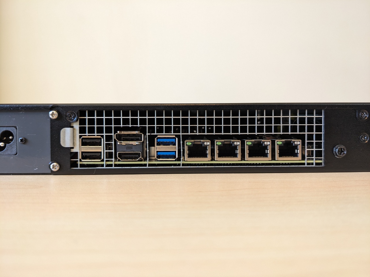
On the back there is a wire mesh panel for cutting out a custom I/O shield, which is handy since I have an off-brand motherboard.
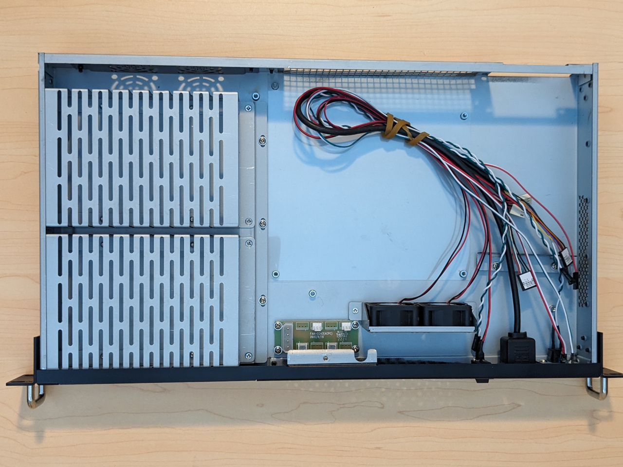
On the inside, it’s configured for 2 x 3.5" hard drives by default. It also includes 2 x 2-pin 12v fans. They are loud like you would find in most managed network switches, but are not jet-engine loud like most servers. The fan controller simply distributes 12v, and has no speed control.
This is not a very common case, and I read everything I could find online about it. In order to help the next person who is searching for it, here are two more random pieces of information which I could not confirm until I had the case in-hand:
- Stand-offs on the case are all 4mm tall and non-removable
- Screw spacing of USB 2.0 front panel connector is approx 30.5mm (from centre of each screw). Stacked USB 3 headers that are 30mm spacing are available online and could be made to work.
Closer look at the Topton N6005 Mini ITX
I chose to use a Topton motherboard with a built-in Intel N6005 CPU for this build, since the alternatives were either too tall, use a socketed CPU, use an old CPU, would require add-in cards to get multiple SATA ports, or were not sold in Australia. All of these would make it far more difficult to complete the small, quiet build which I was aiming for.
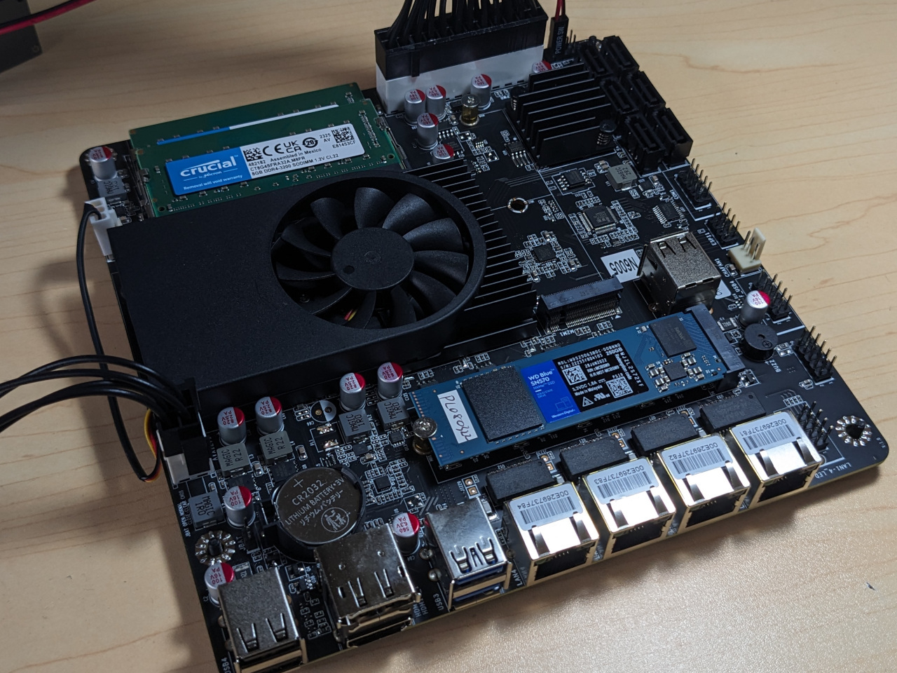
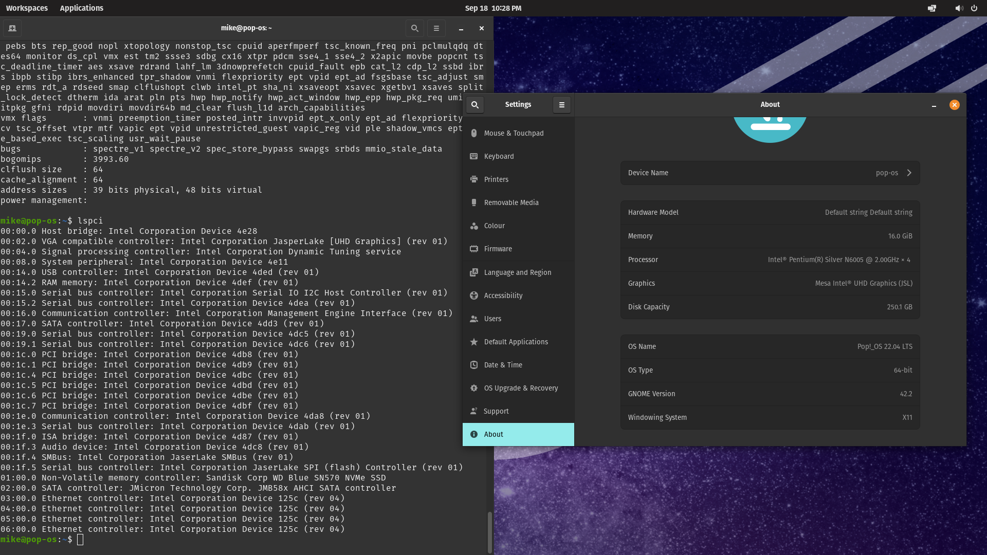
From the few threads online about this board, I gathered that it is fussy about RAM compatibility, so I booted it up at the first opportunity with an SSD containing Pop!_OS to check that it worked. It’s not my use case, but this motherboard would definitely be viable as a lightweight desktop.
The specific memory I used was a 16 GB kit with the model number CT2K8G4SFRA32A. According to Intel’s product documentation, the N6005 only supports 16 GB maximum, and while I could find claims that higher-capacity memory does work, I couldn’t find anybody who posted actual part numbers.
I was happy to find that the built-in cooler is inaudible at idle loads. This was a bit of a risk: the cooler doesn’t have standard dimensions, so I couldn’t have easily replaced it with an alternative if it was noisy. Based on other people’s experiences with this board, I re-pasted the cooler with Noctua NT-H1 thermal paste, to hopefully help keep temperatures down at higher loads so that the fan will not need to spin up as much. I also avoided using the M.2 slot which receives the most hot air from the cooler.
Topton also sells an N5105 variant which appears to be more popular (more info here), as well as an alternative layout which has a PCIe slot instead of a second M.2 slot.
Custom power supply adapter plate
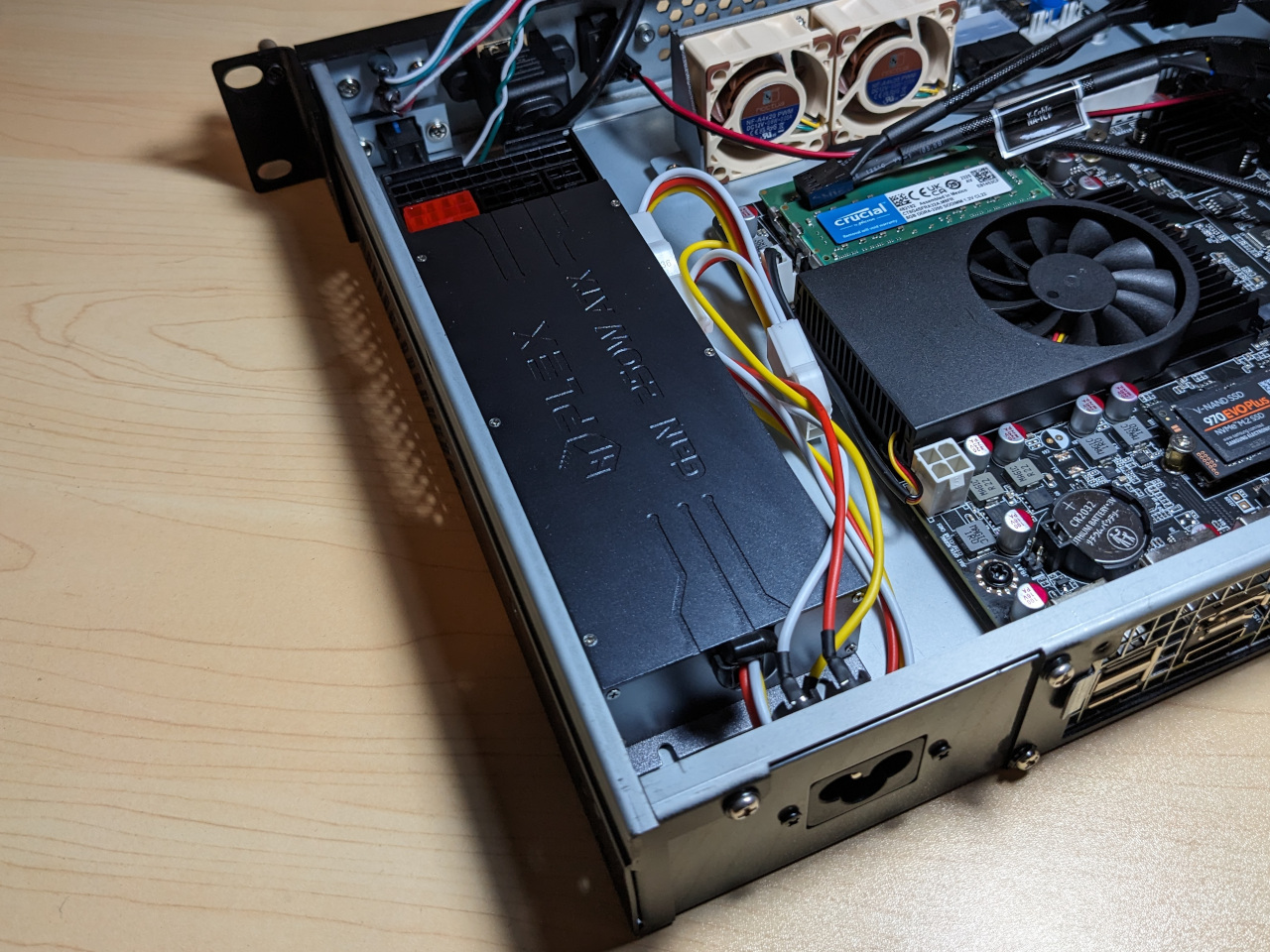
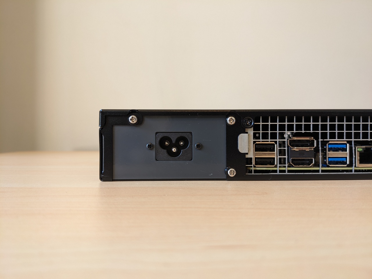
The case is designed for a Flex ATX power supply, which is not what I’m using. I’ve instead opted to use a passively-cooled HDPLEX GAN 250W power supply, which ships with both an IEC C6 and IEC C14 cable.
I needed to choose one of these cables, and figure out how to securely mount it to the case.
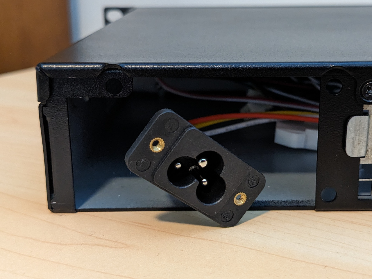
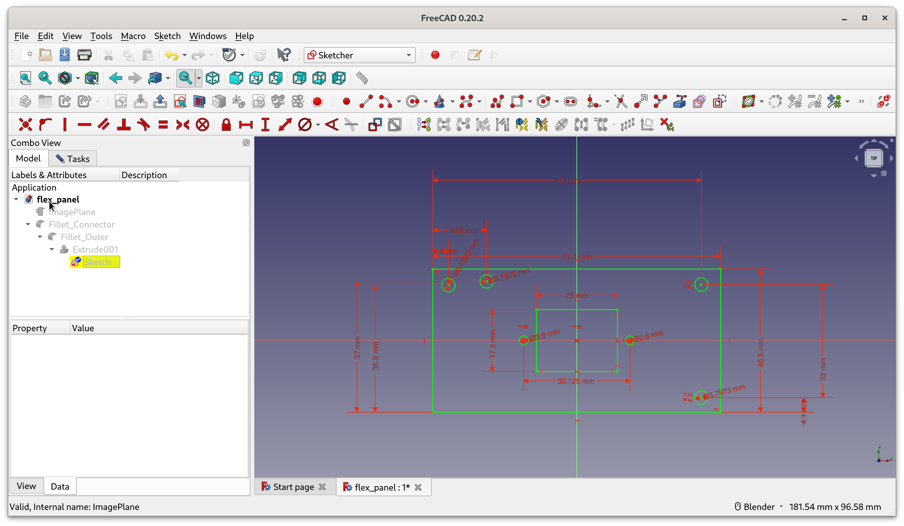
I designed an adapter plate in FreeCAD around the included IEC C6 cable, since it had threaded holes, and screws were included.
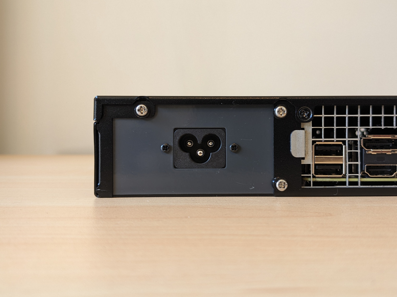
I ordered it from a prototype supplier in laser cut 1mm steel, painted in matte black.
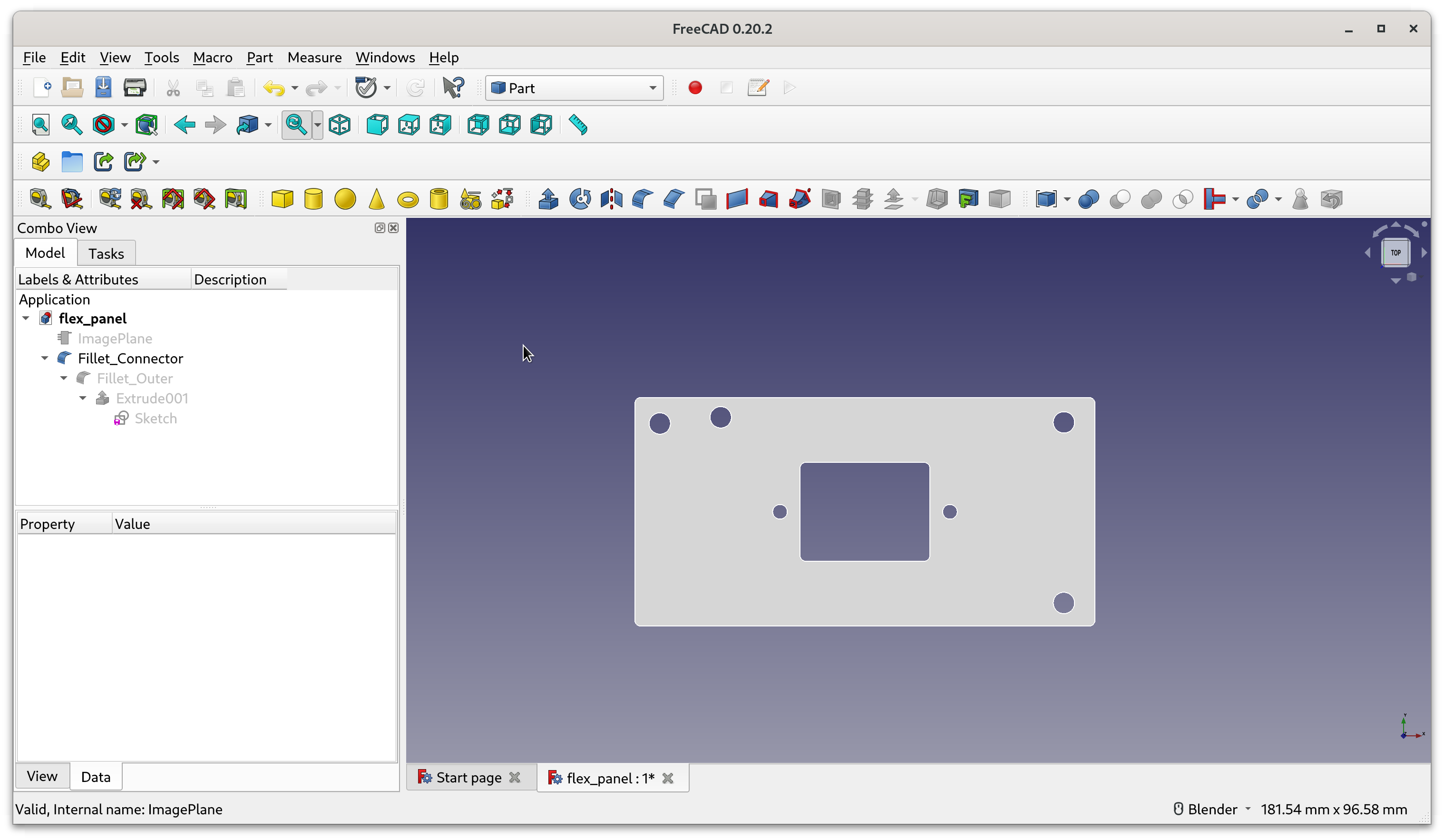
This is the first time I’ve used FreeCAD to design a part, and parametric CAD certainly has a learning curve. For this build, it was well worth it, since the result is better (and safer) than anything I could have improvised.
At the time of writing this post, HDPLEX sells plates for mounting their IEC C14 cables in cases accepting SFX and ATX power supplies, but none for cases which accept Flex ATX power supplies.
Custom fan controller
Cooling this build quietly was always going to be a challenge. The case shipped with 2 x 12 V fans, and had a simple splitter which ran them at max speed, which was just too loud.
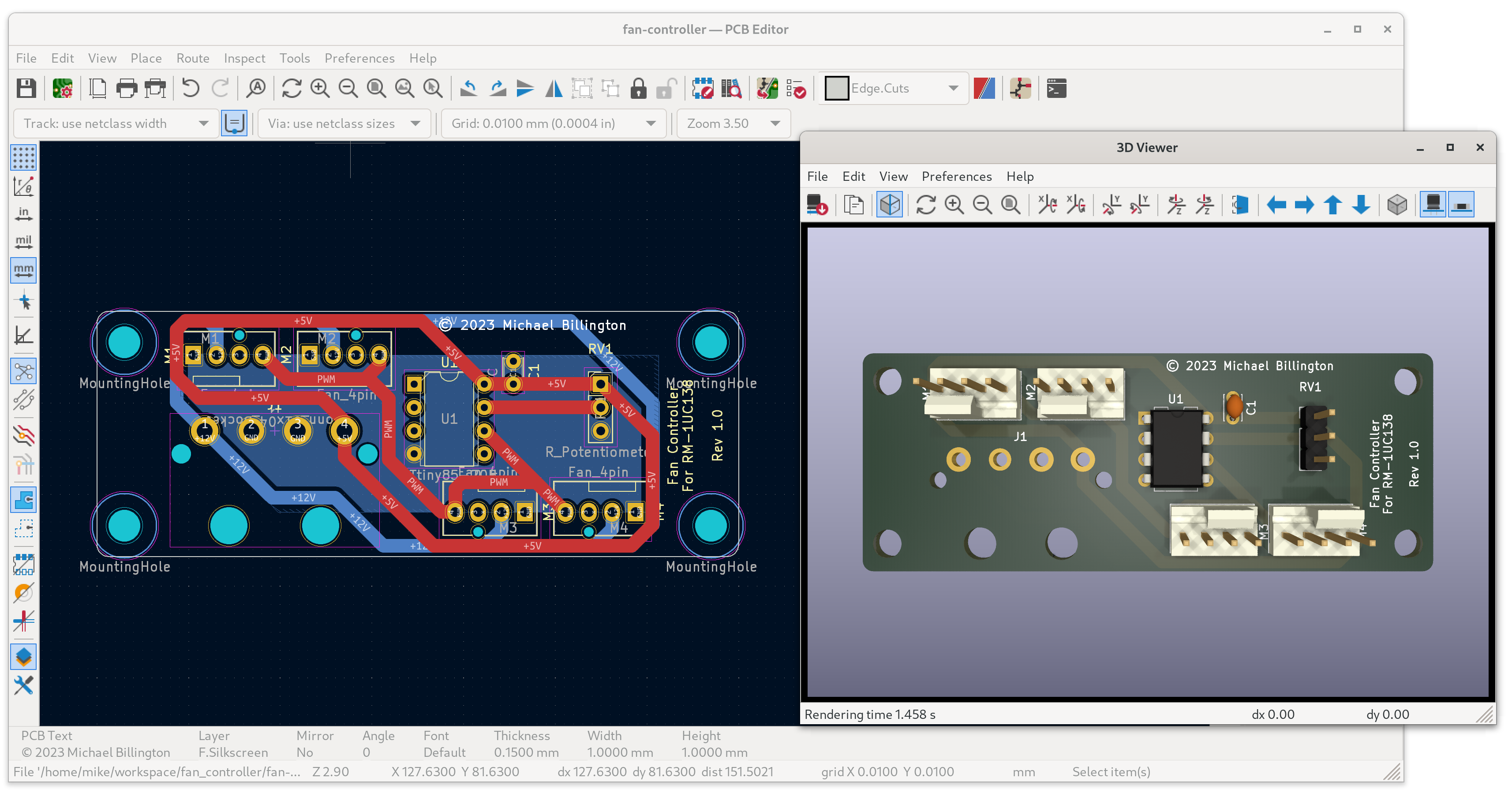
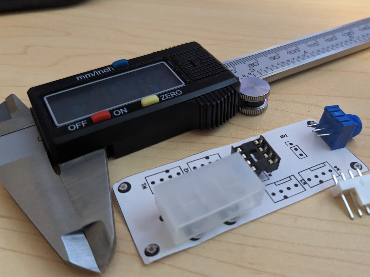
I designed a replacement fan controller in KiCad, which allows me to upgrade to high-quality 4-pin fans with PWM speed control, and to set the speed using a potentiometer. I wrote about prototyping this in a separate blog post.
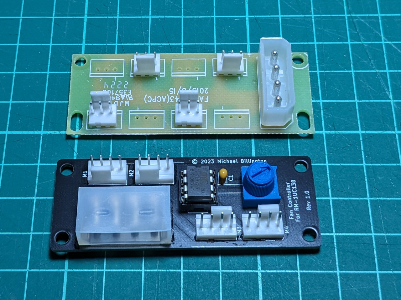
This photo shows the custom controller alongside the original one it replaces.
As you can probably guess, I’ve designed this to use the same mounting location, at the front of the case. My power supply has no Molex connectors, so I’m using a SATA-Molex power adapter.
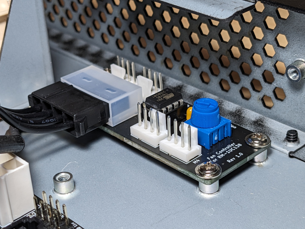
The main drawback to this simple design is that once I close up the case, I can no longer adjust the fan speed.
Final assembly
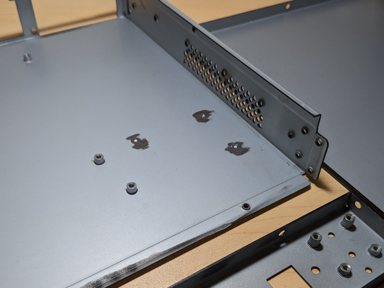
Before continuing any further, I took apart the case completely and deleted three standoffs with a belt sander, to leave a flat area for power supply installation later.
Once I got the case back together, the motherboard went in first. I raised it by 1mm using plastic washers, hoping to line it up better with the I/O shield included with the motherboard.
The I/O opening for 1U servers is narrower than standard PC builds, so I needed to cut the I/O shield, which I unfortunately did not do correctly.
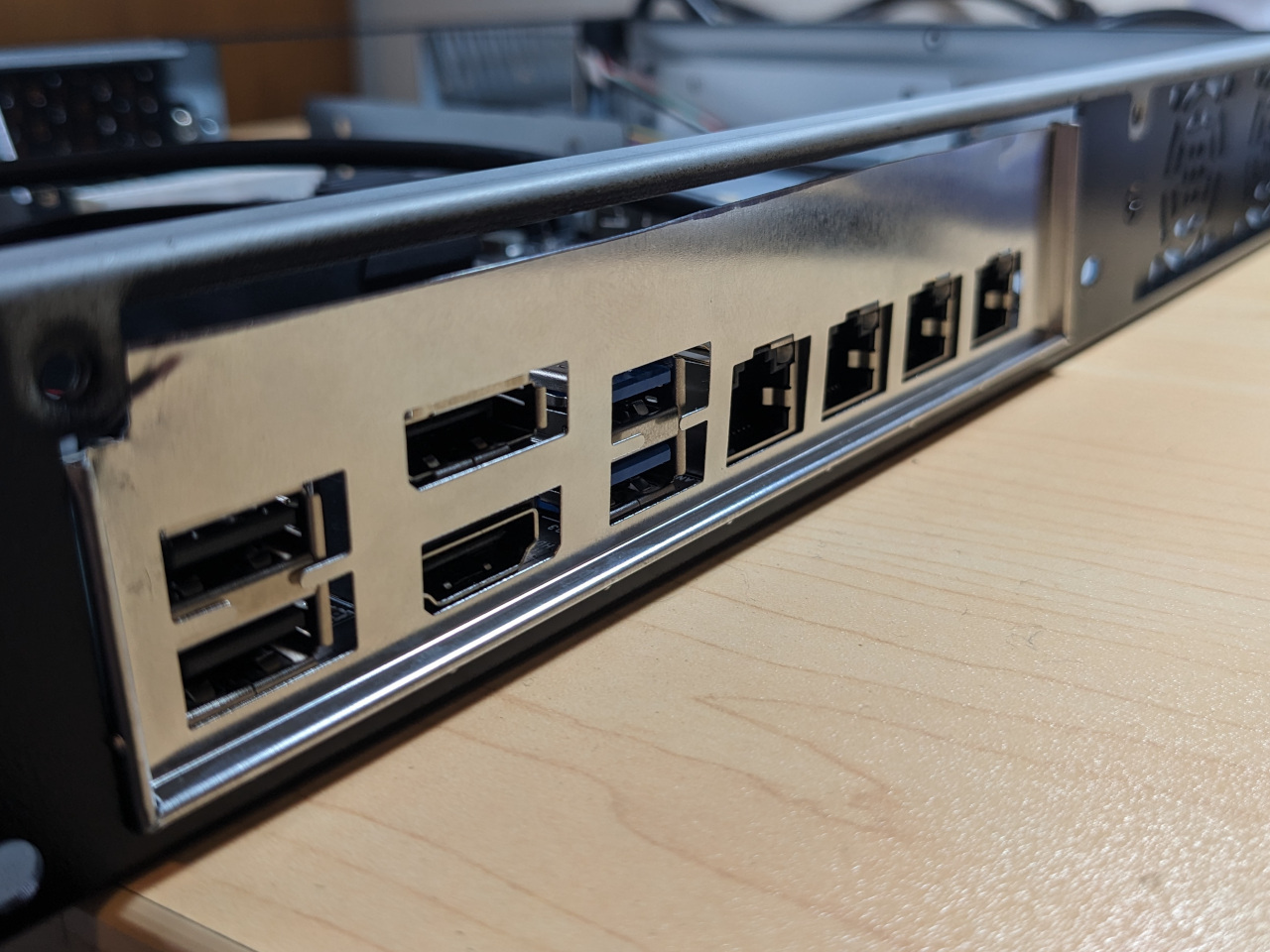
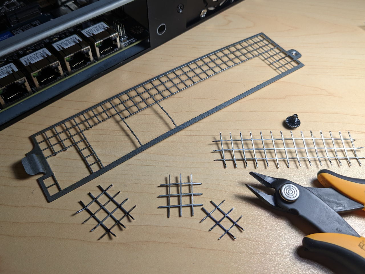
Since that did not work, I carefully marked and cut out the wire mesh I/O shield included with the case instead. I still left the motherboard raised up on 1mm washers, though this is not necessary anymore. You need to use slightly longer screws if you try this.
After that I installed the four case fans, plus the fan controller. I’m using a front-to-back airflow, with 2 x 40mm fans mounted at the front, and 2 x 40mm fans at the back. I added a Y splitter to the back fans, which did not have long enough cables to reach the fan controller.
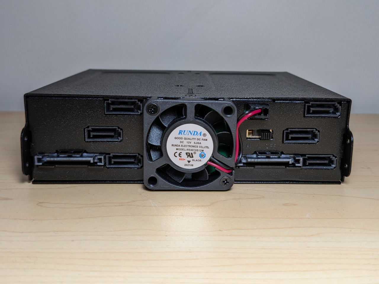
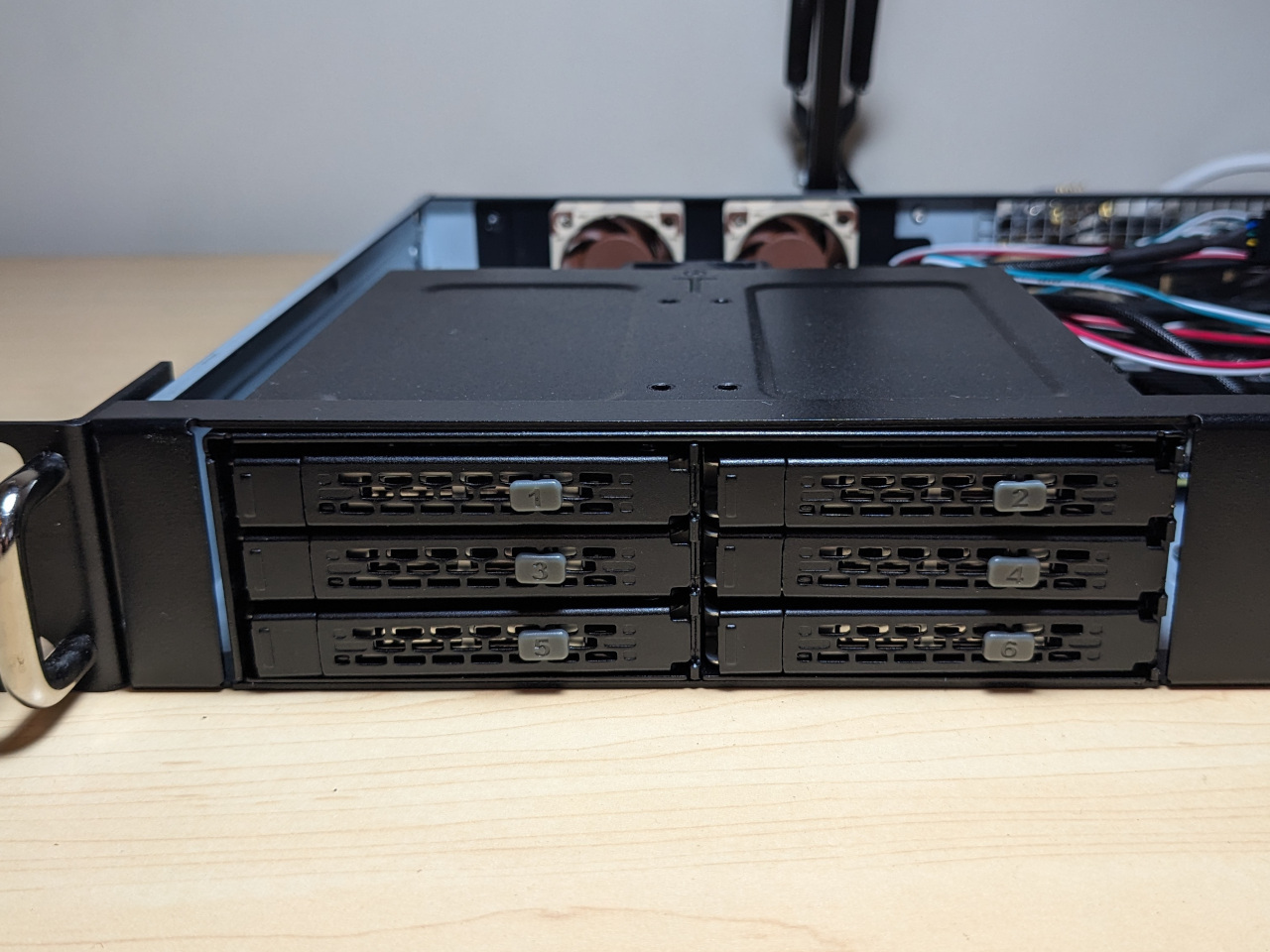
The next component I installed was the drive cage. It’s worth mentioning at this point that the drive cage also has a fan header, which is the same as a 3-pin header that you would find on a PC motherboard. It supplies a different voltage for each of the speed settings. Medium is approximately 7.5 volts and is relatively quiet with the included “Good quality DC fan” fan, and high speed is 12 volts. I set mine to off but left the fan installed.
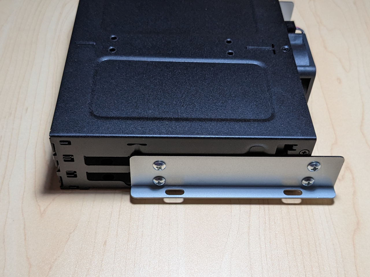
To install items into the 5.25" bay in this case, you attach a bracket, then fasten it from above. The bracket allows the depth to be adjusted as well.
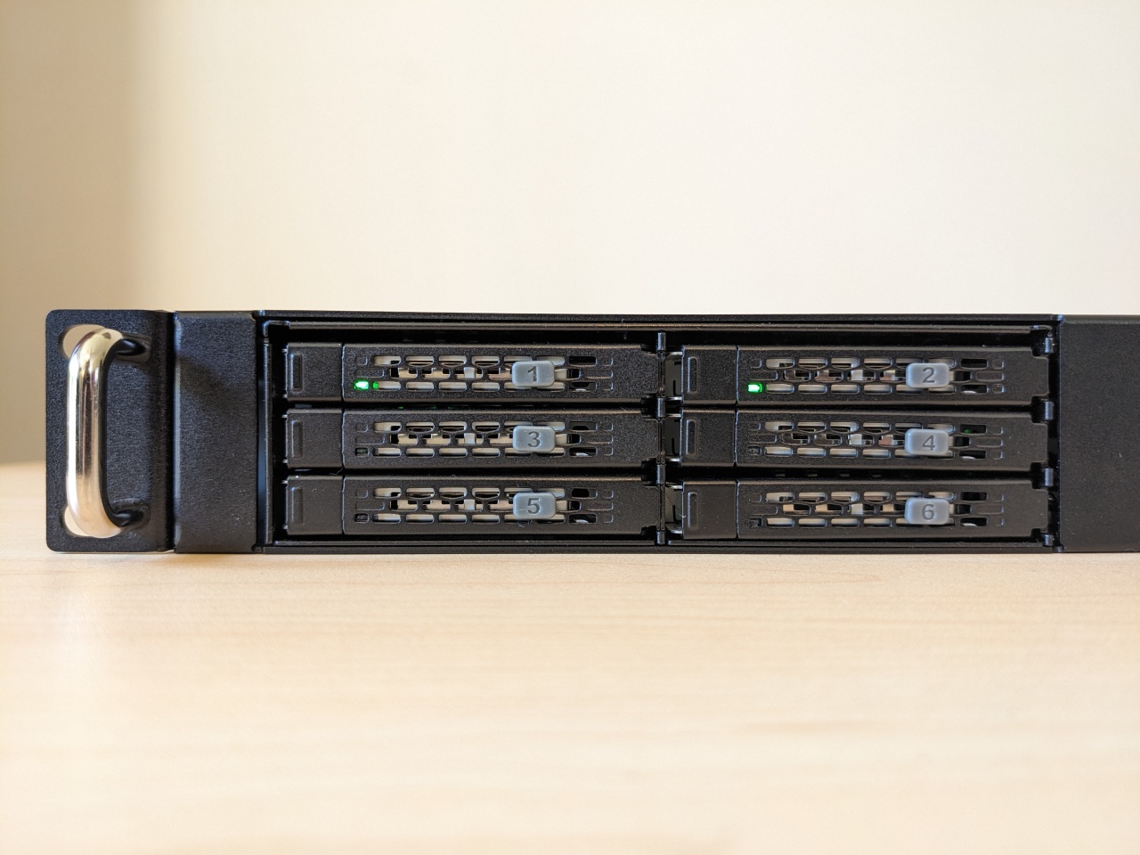
I also installed disks in the drive cage at this point, and numbers on the front. Disk 1 is connected to SATA0 on the motherboard, disk 2 is connected to SATA1, and so on.
Next was the power supply. I installed the custom plate for the power connector, and also installed the mounting plate on the bottom of the PSU so that it would have a flat surface. After confirming that it would fit, I cleaned both surfaces with alcohol, and applied double-sided tape.
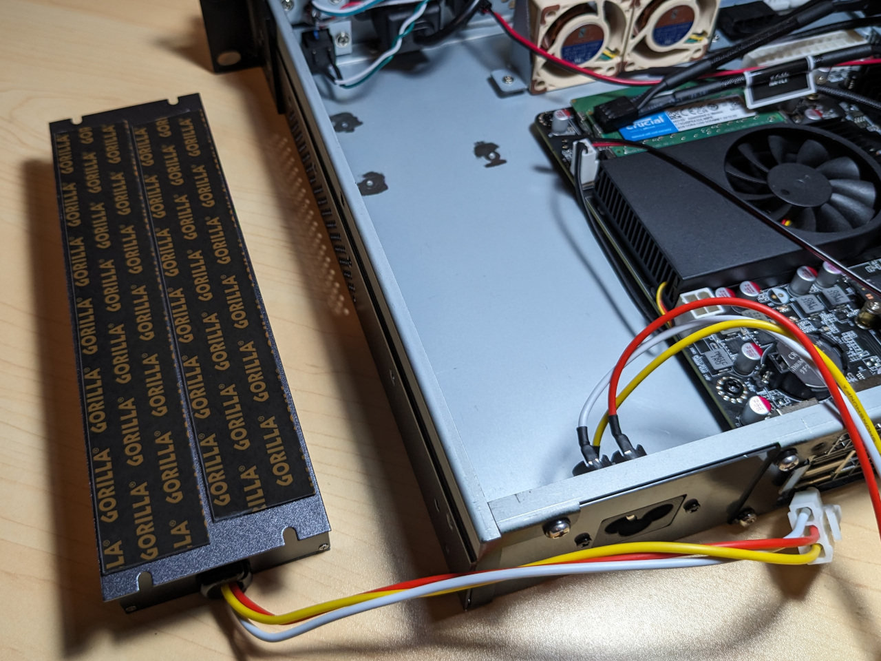
I then followed a rehearsed path to drop the PSU into place. There is no opportunity to adjust it once it sticks.
At this point I connected everything up and booted up the system to start checking for problems, since it’s easier to troubleshoot in this state. Two modifications I made here were to disconnect the bright red HDD LED, and to introduce a SATA power Y splitter, because the power supply SATA cables were stretched to the limit.
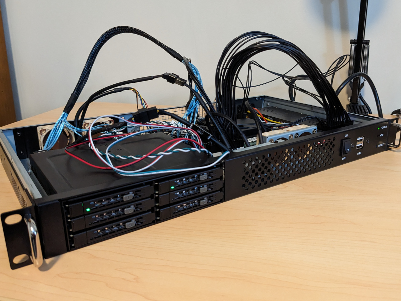
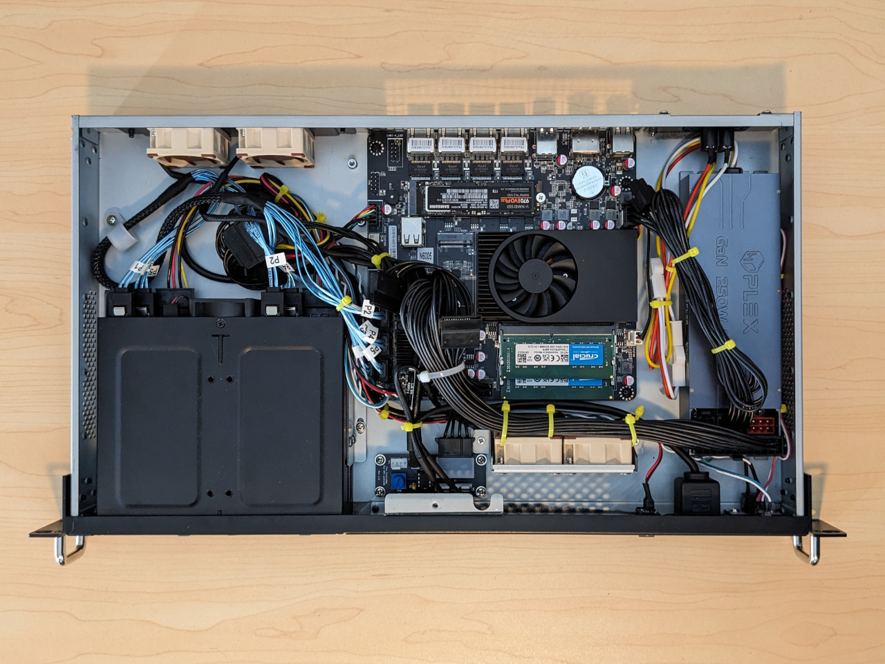
It took a lot of work (and cable ties) to arrange the cables flat so that the case could close. In defence of cable ties, they do make maintenance more difficult, but that’s a worthwhile trade-off for keeping cables clear of airflow paths, fan blades, and the guillotine-like action of the top cover sliding shut.
Completed build
After closing the case, the build is, 434mm × 254mm x 44mm, or 4.8 litres, excluding rack ears.
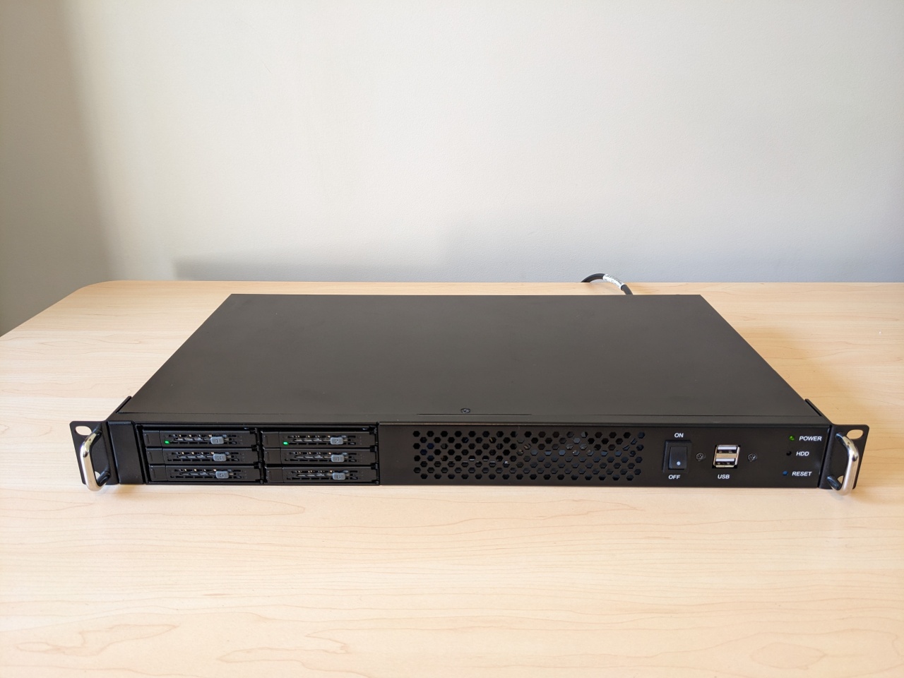
This is how it appears from the front.
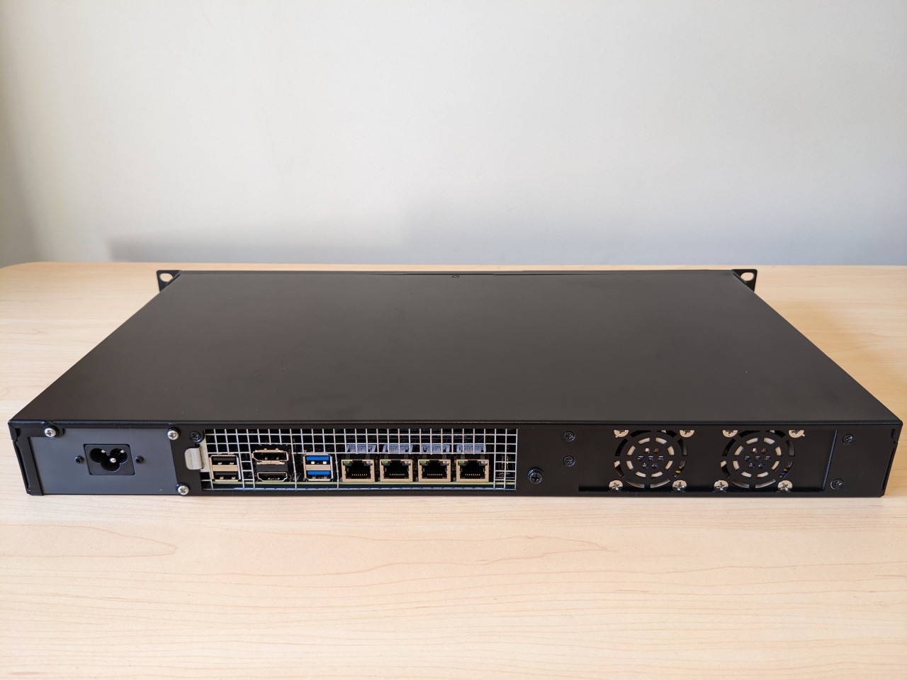
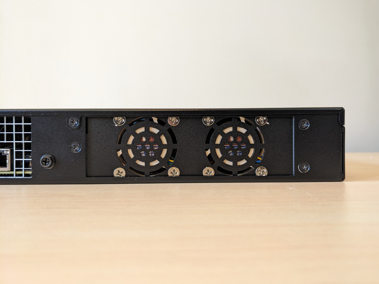
And this is how it appears from the back.
Software
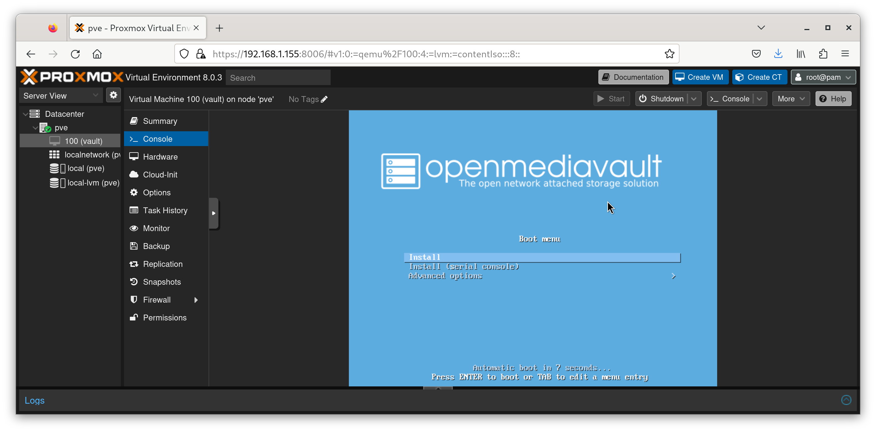
I’m starting with Proxmox, with OpenMediaVault deployed as a virtual machine. I haven’t used either of these before, but both are Debian-based and provide convenient web front-ends to the tools I would otherwise be configuring on the command-line.
I’m passing through the disks as block devices. Running the NAS like this should make it possible to provision extra workloads which need their own SATA disks in future, or to switch from OpenMediaVault to stock Debian if necessary, all without connecting a monitor.
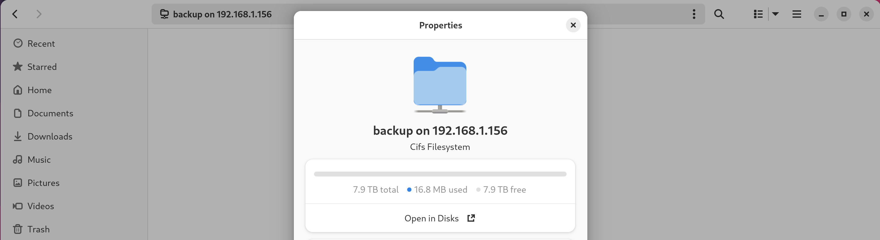
Within OpenMediaVault, I’ve configured Linux software RAID, with an ext4 filesystem, shared via Samba, and can access that file share over the network.
I’ve enabled some basic power management features such as C-states. The system idles in the range of 12-14 watts measured from the wall, and goes up to 20 watts when moving files around.
I don’t need a lot of disk capacity, so I’ve been able to preserve a useful property of my old setup, where every disk in the system has a full copy of the data, in a format which can be understood by a normal Linux system. This it makes single-disk recovery possible using any surviving disk from the system on practically any computer, and that disk can be from either an offline copy or one of the disks in the RAID mirror.
I haven’t tested the process of making an offline copy of the backup volume, but that will be up next.
Wrap-up
This is possibly the most effort I’ve ever put into a PC build. The only unexpected issue I encountered is how heavy it is, and wont be rack-mounting it until I get some generic rails.
The computer uses a strange mix of parts, but meets my requirements well. I hope that by writing this up, I’ll be providing some useful notes to anybody attempting to build something similar.
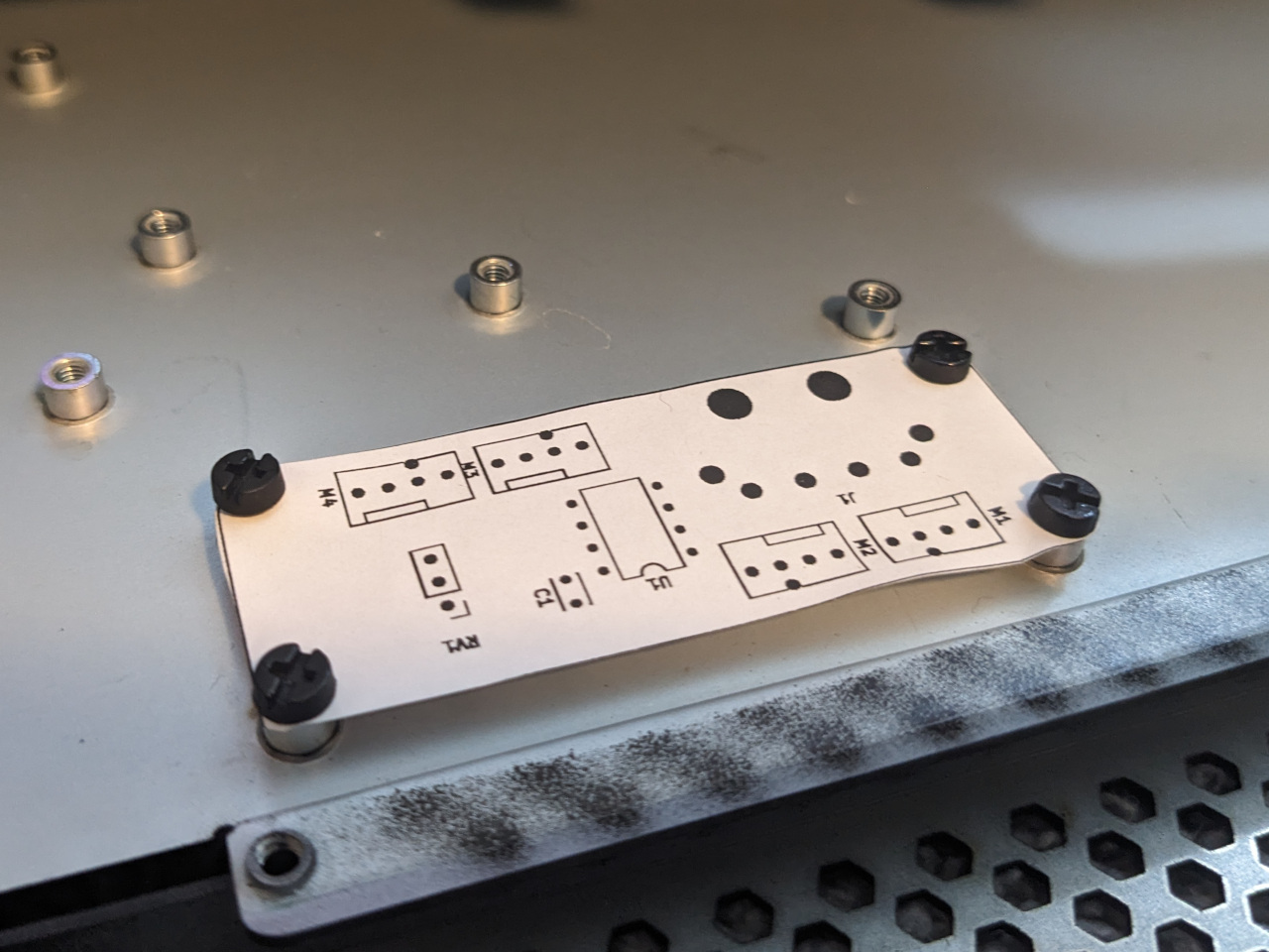
This project also gave me a chance to practice my entry-level CAD skills to build something which I’ll actually be using. I find a lot of utility in paper prototyping, and printed each design in 1:1 scale to check the physical dimensions before ordering anything.
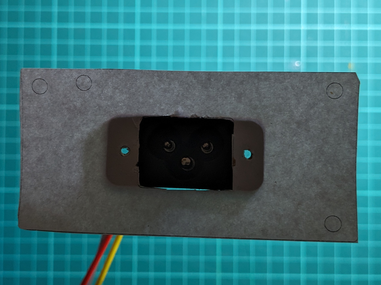
For the circuit board, I used a print-out to check each part footprint, as well as the hole locations for fitting it in the case.
As with many of the projects which I blog about, I’ve put the design files up on GitHub. The fan controller is at mike42/fan-controller-athena-power, while the Flex ATX adapter plate is at mike42/flexatx-adapter-hdplex.