I’ve been using 6502 assembly for some hobby projects recently, but only testing in an emulator. It’s about time to target some real hardware, so for the past few weeks I’ve been following Ben Eater’s 6502 computer tutorial.
I am a complete beginner when it comes to electronics, so I spent a bit of time making useless circuits to toggle LED’s, then jumped right in to building the simplest possible circuit exercise a 65c02 CPU, known as a NOP generator. I used a 555 timer and an inverter to get a 3Hz clock, which is quite a bit slower than my desktop PC.
I then extended the circuit to run NOP instructions from a ROM. I generated a ROM filled with the 6502 NOP instruction by printing a character to a file, then concatenating the file to itself times to fill the ROM.
$ printf '\xEA' > rom-original.bin
$ dd if=rom-original.bin of=rom-original.bin bs=1 seek=1 count=32768
I am using an open-source tool called minipro with a TL866II+ programmer to burn the ROM.
$ minipro -p AT28C256 -w rom-original.bin
Found TL866II+ 04.2.86 (0x256)
Warning: Firmware is out of date.
  Expected  04.2.123 (0x27b)
  Found     04.2.86 (0x256)
Erasing... 0.02Sec OK
Protect off...OK
Writing Code...  7.44Sec  OK
Reading Code...  0.77Sec  OK
Verification OK
Protect on...OK
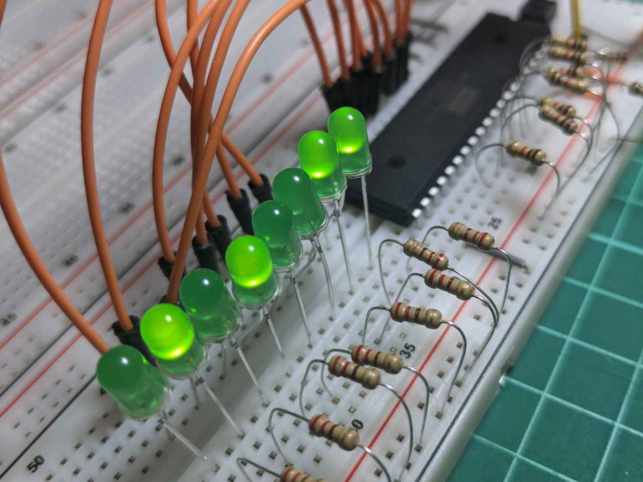
Next, I tried to extend the circuit to blink some LED’s based on a programmed sequence. When I ran the program, the 65c22 I/O chip warmed up, and my row of LED lights did not blink. It turns out that I had mixed up the meaning of VCC and VSS, and applied a reverse voltage to the chip. I found a post from somebody else who had made the same mistake, and corrected it before the chip was damaged.
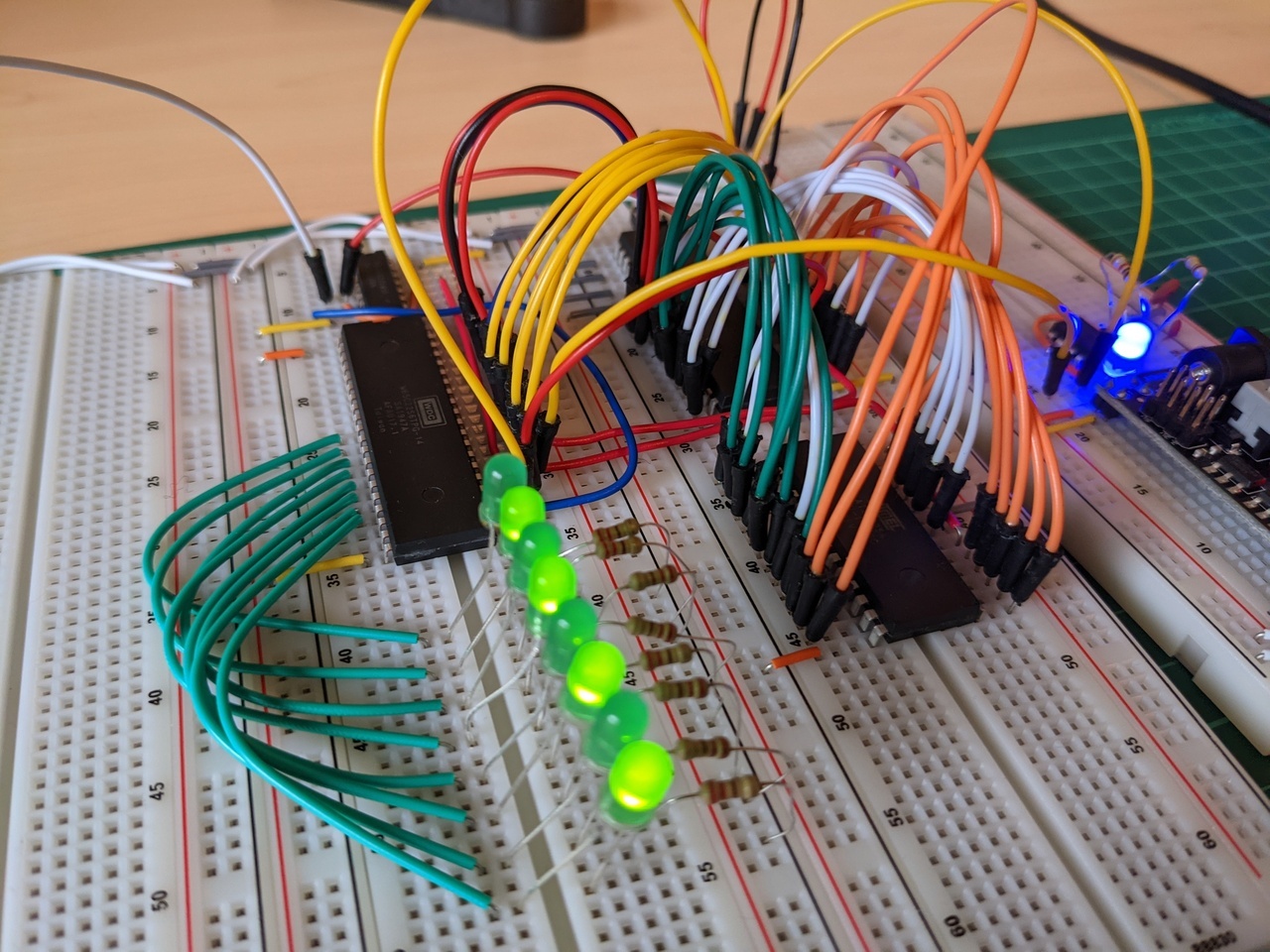
This program worked well initially, but the computer would sometimes crash when running at this slow speed, so I started running it with a 1MHz or 1.8MHz oscillator instead. I now know that this is because I had plugged the 65c02 and 65c22 clock inputs into the 555 timer output, when I should have been running it through the inverter first. The rising-edge and falling-edge times of the 555 timer are apparently not fast enough to clock these chips reliably.
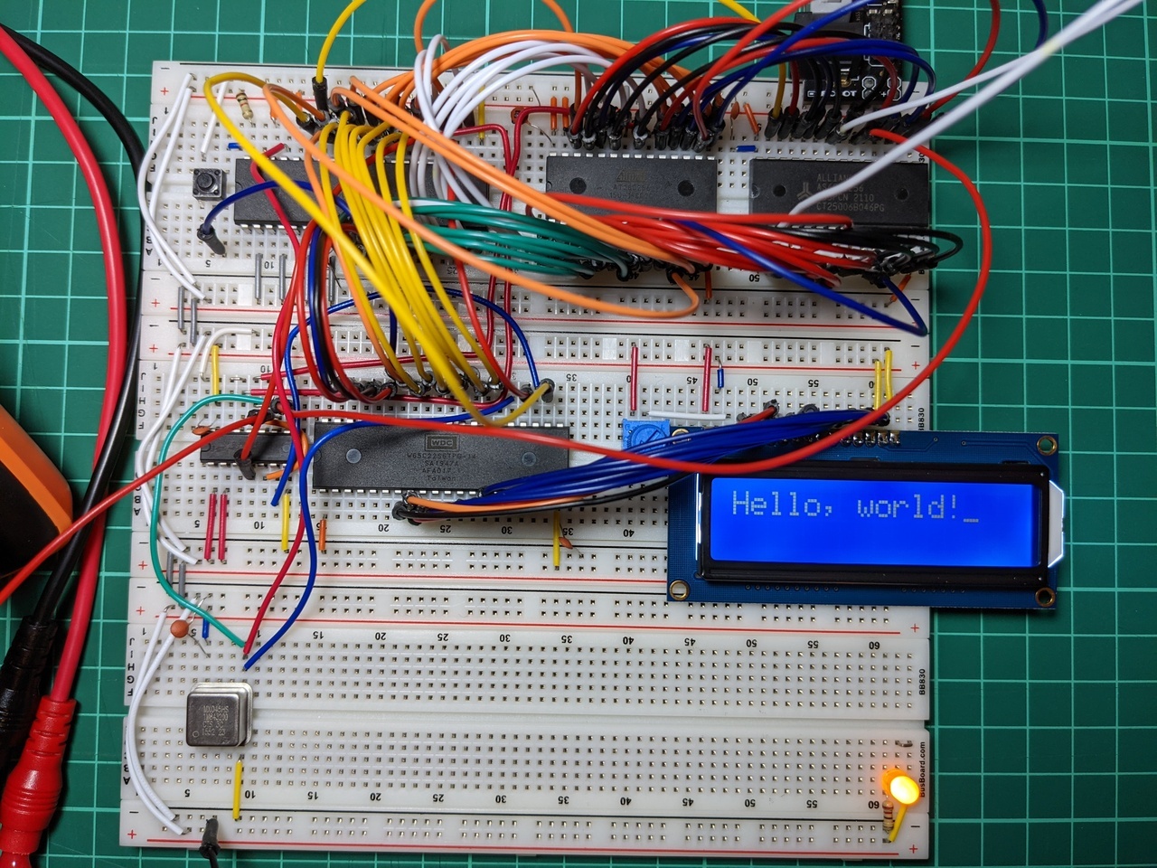
The next step was to add an LCD and some RAM. My first attempt did not work, and it took me a few hours of troubleshooting to rule out any hardware problems. In the end it was a simple programming error, where I had used a jmp instruction instead of jsr in my test program.
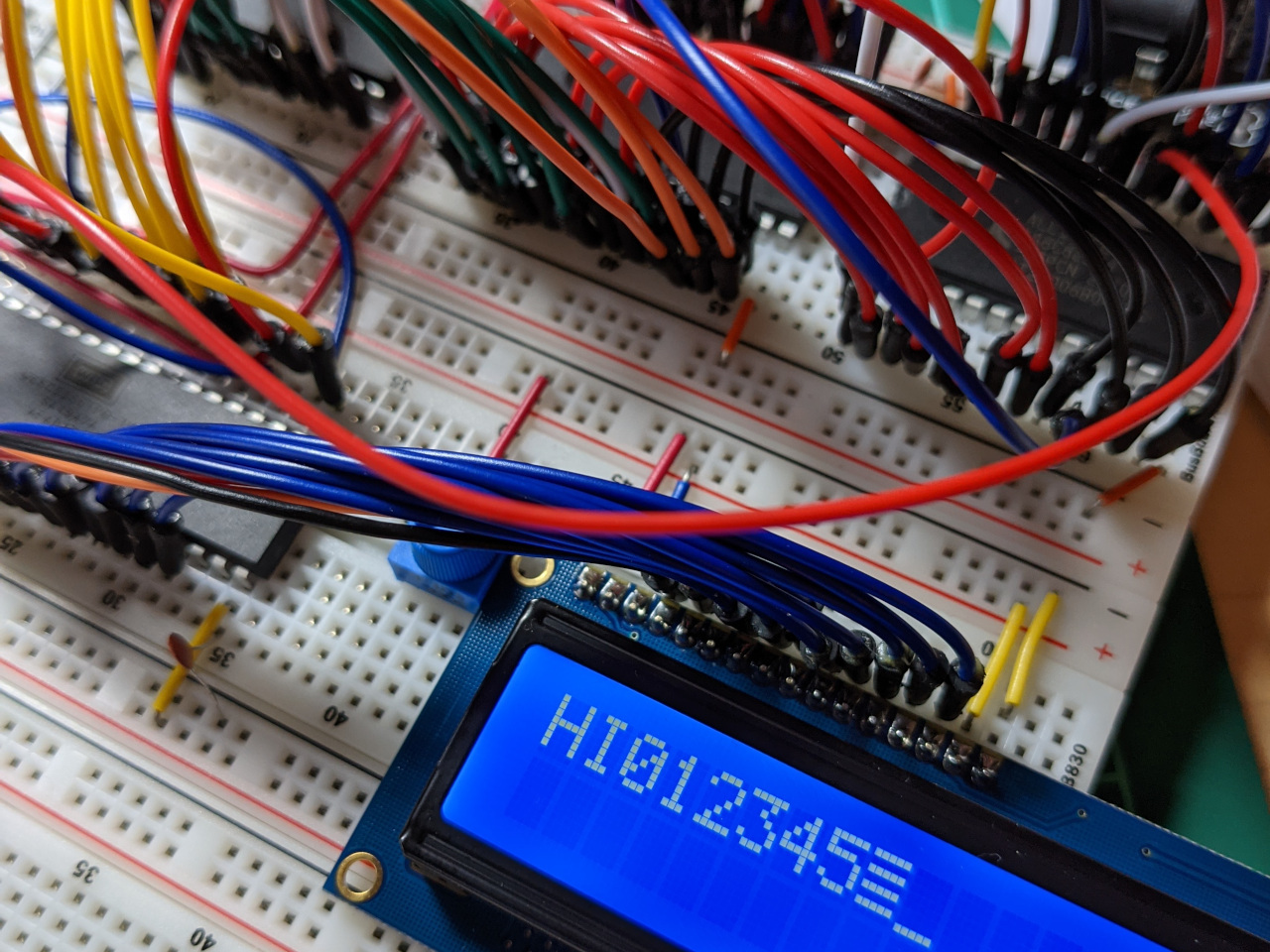
So it’s not much, but it works! Based on some of the problems that I had while building this, it was definitely a good idea to start with a known-good design on a breadboard.
I’ve got a few ideas (and components) for extending this computer already, and I’m hoping to learn a thing or two about hardware and software along the way.