In my last blog post, I wrote about the 8-bit computer which I’ve been building, using an existing design by Ben Eater. The I/O capabilities of the original design are rather limited, so one of the first enhancements I’m making is to add a serial port.
Hardware
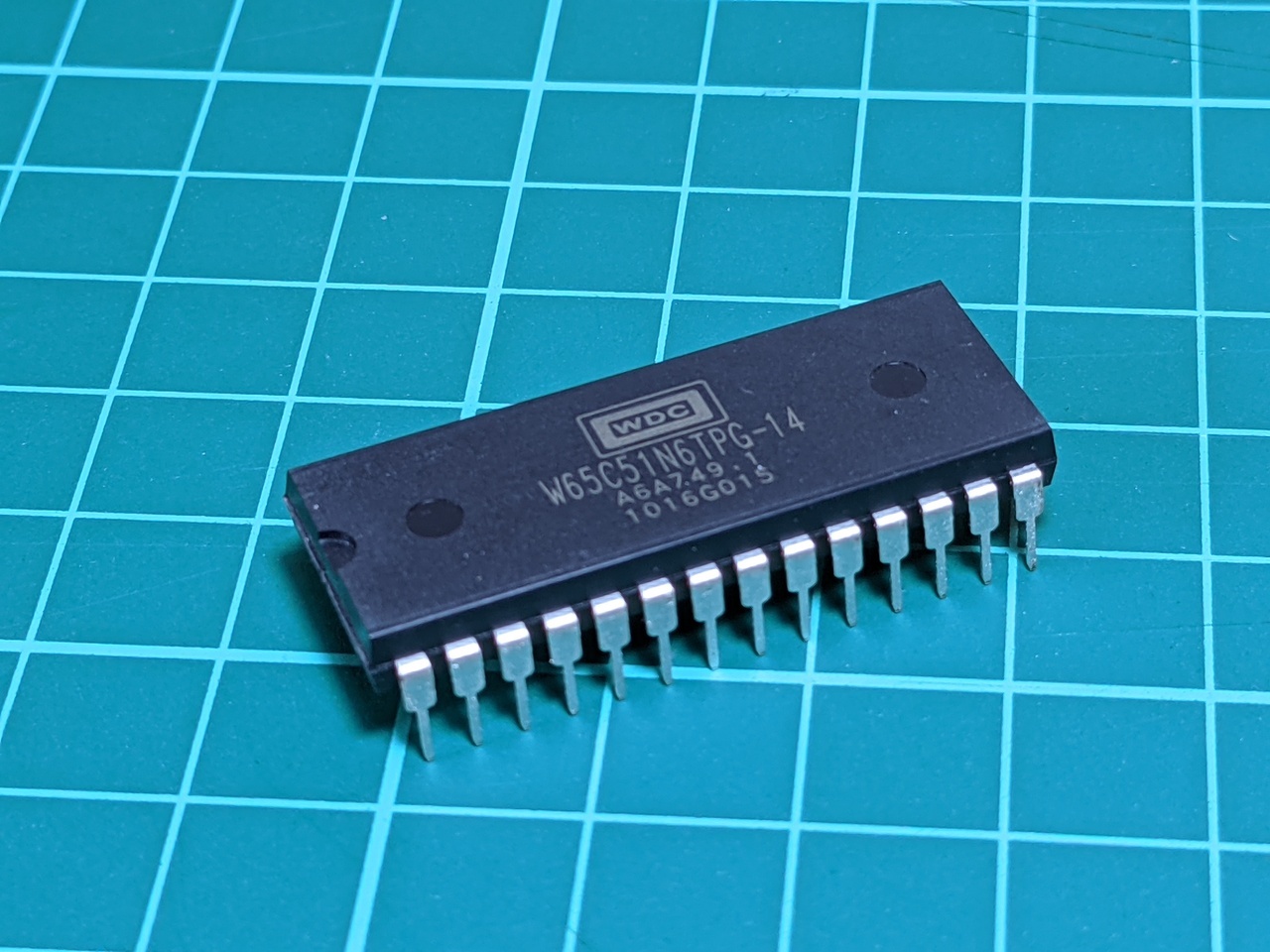
The main chip I am adding is the WDC 65C51N ACIA, which is a modern version of the MOS 6551. Versions of this chip have been on the market for around 40 years, and lots of classic computer designs use some version of it for serial output. I bought this one new, and the date code indicates that it was manufactured 11 years ago, so it’s a fair guess that they are not selling as fast as they used to.
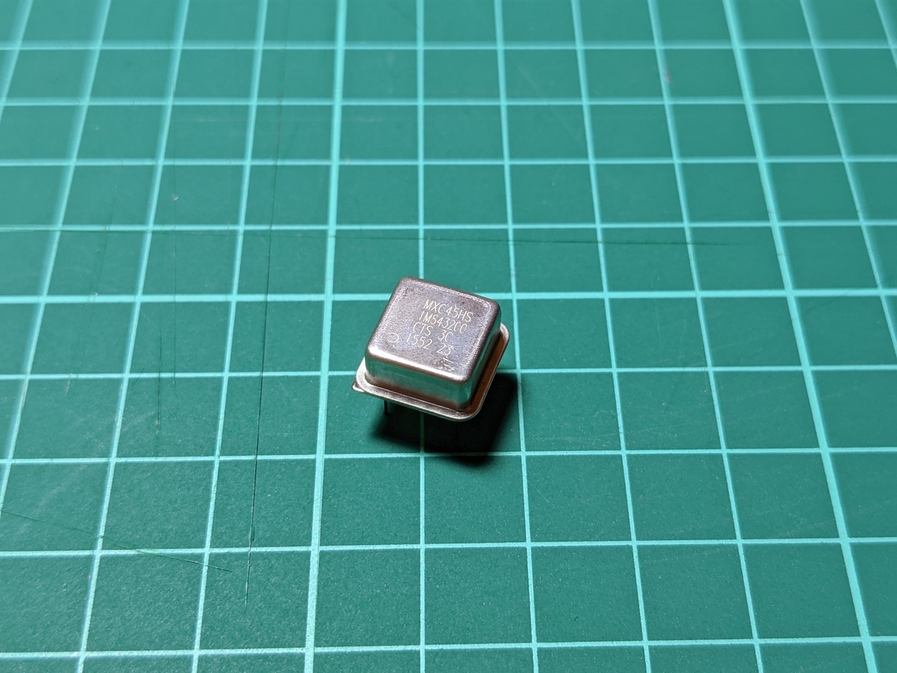
I also needed a 1.8432 MHz oscillator, which I used to clock both the computer and the UART.
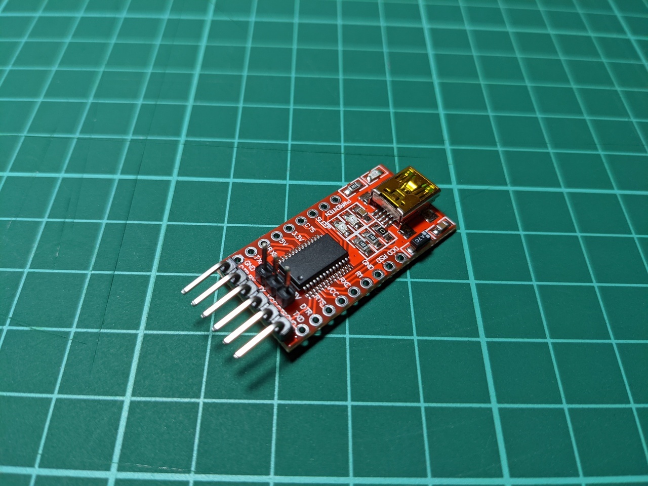
Lastly, I used a USB/UART module to interface with a modern computer. This module hosts a FT232RL chip, and the pins on this one are DTR, RX, TX, VCC, CTS and GND.
Address decoding
The 65C02 CPU in my computer uses memory-mapped I/O, so I needed to fit this new I/O chip into the memory map before I could start using it.
The original design uses a single-chip solution for address decoding, where the select lines for the ROM, RAM, and a 65C22 VIA chip are connected via 3 NAND gates.
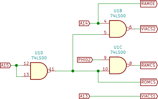
This leaves an unused space between address 4000 and address 5FFF.
| Address | Maps to |
|---|---|
| 8000-FFFF | ROM |
| 6000-7FFF | I/O - 65C22 VIA |
| 4000-5FFF | Not decoded |
| 0000-3FFF | RAM |
The 65C51 ACIA has two chip select inputs: one active-high and one active-low, much the same as the 65C22 VIA. All I needed to do was invert A13, and there was an unused NAND gate in the existing design which I could use for it.
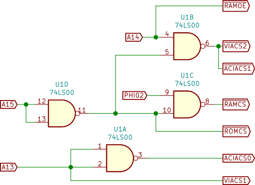
This places the 65C51 in the unused address space. It’s not exactly efficient to assign 8KB of address space to a device which needs 4 bytes, but it does work.
| Address | Maps to |
|---|---|
| 8000-FFFF | ROM |
| 6000-7FFF | I/O - 65C22 VIA. |
| 4000-5FFF | UART - 65C51 ACIA |
| 0000-3FFF | RAM |
While editing this blog post, I also re-read Garth Wilson’s address decoding guide for the 6502, which shows some alternative schemes for achieving this.
Wiring
I’m using the following wiring between the 65C51 and the USB/UART module.
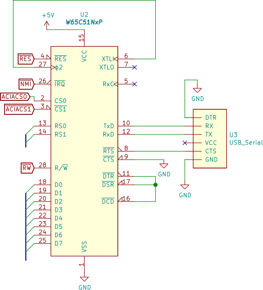
Note: The the two clock inputs are connected to the 1.8432 MHz oscillator, which is not shown correctly here.
Software
This particular revision of the 6551 has some hardware bugs, though they are well-documented and can be worked around in software. Most of the excellent example code online is aimed at older (less buggy) revisions.
After four attempts, I was able to write an assembly-language program which could produce some output. The information on this 6502.org thread, and this 6502.org comment were the most accurate for my hardware setup.
I’m using this code to set up the ACIA for 8-N-1 communication at 19,200 bytes per second, with no interrupts.
ACIA_RX = $4000
ACIA_TX = $4000
ACIA_STATUS = $4001
ACIA_COMMAND = $4002
ACIA_CONTROL = $4003

reset:
	; ... other stuff
	; ACIA setup
	lda #$00
	sta ACIA_STATUS
	lda #$0b
	sta ACIA_COMMAND
	lda #$1f
	sta ACIA_CONTROL
	; ... other stuff
To send, I needed to add a delay between bytes, since the hardware bug prevents the transmit bit in the status register from operating correctly. I found some code with nested loops, but it only worked after increasing the delay far beyond what should have been necessary. An alternative work-around is to generate a timed interrupt from the 65C22 VIA, which I’m hoping to try later.
; print A register to ACIA
; Based on http://forum.6502.org/viewtopic.php?f=4&t=2543&start=30#p29795
print_char_acia:
  pha
  lda ACIA_STATUS
  pla
  sta ACIA_TX
  jsr delay_6551
  rts

delay_6551:
	phy
	phx
delay_loop:
  ldy #6 ; inflated from numbers in original code.
minidly:
  ldx #$68
delay_1:
  dex
  bne delay_1
  dey
  bne minidly
  plx
  ply
delay_done:
  rts
I am using this routine to receive characters. It will block until the next character is received, and I will most likely need to replace this with something interrupt-driven once I start to add more complex programs.
; hang until we have a character, return it via A register.
recv_char_acia:
  lda ACIA_STATUS
  and #$08
  beq recv_char_acia
  lda ACIA_RX
  rts
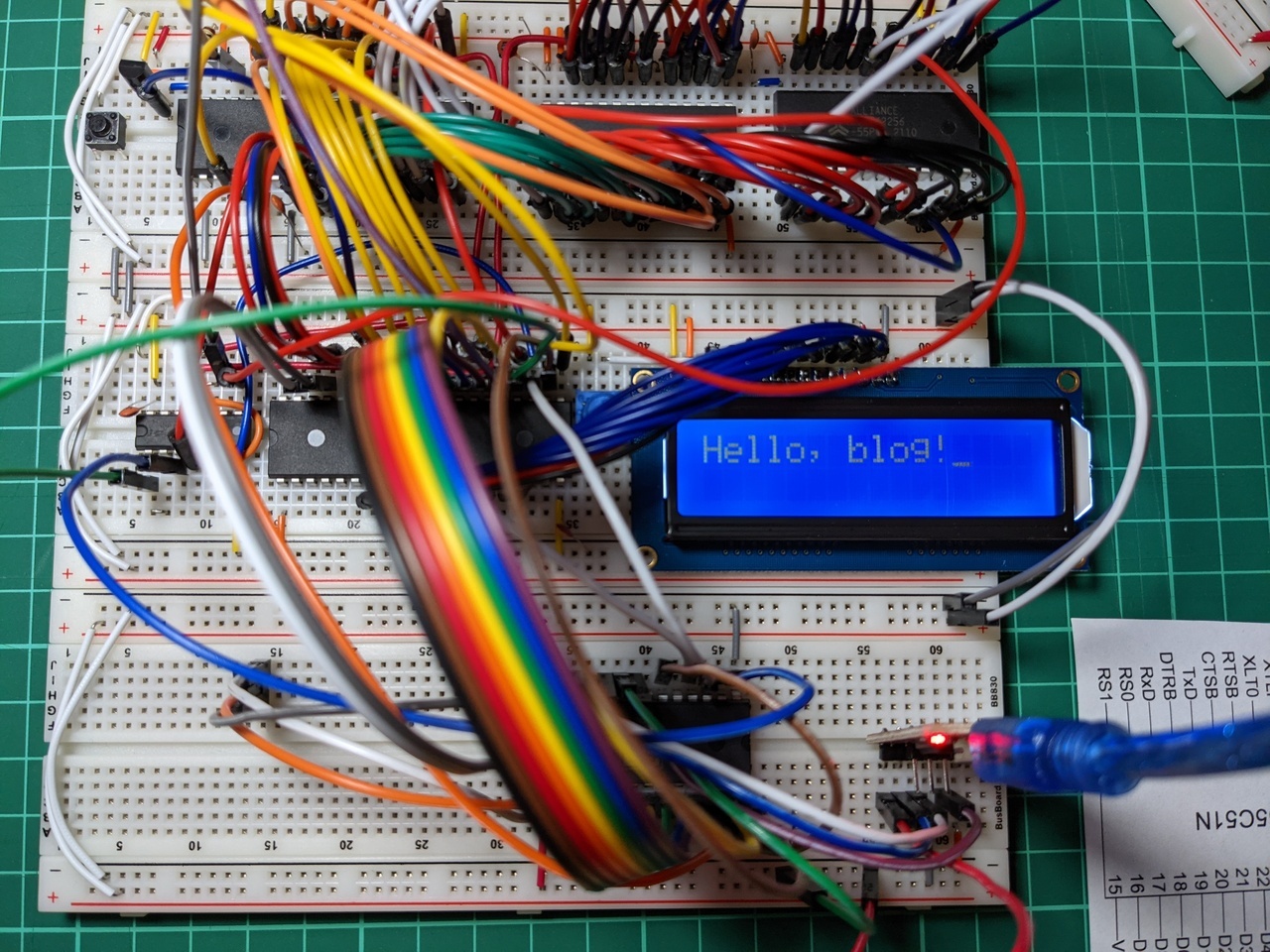
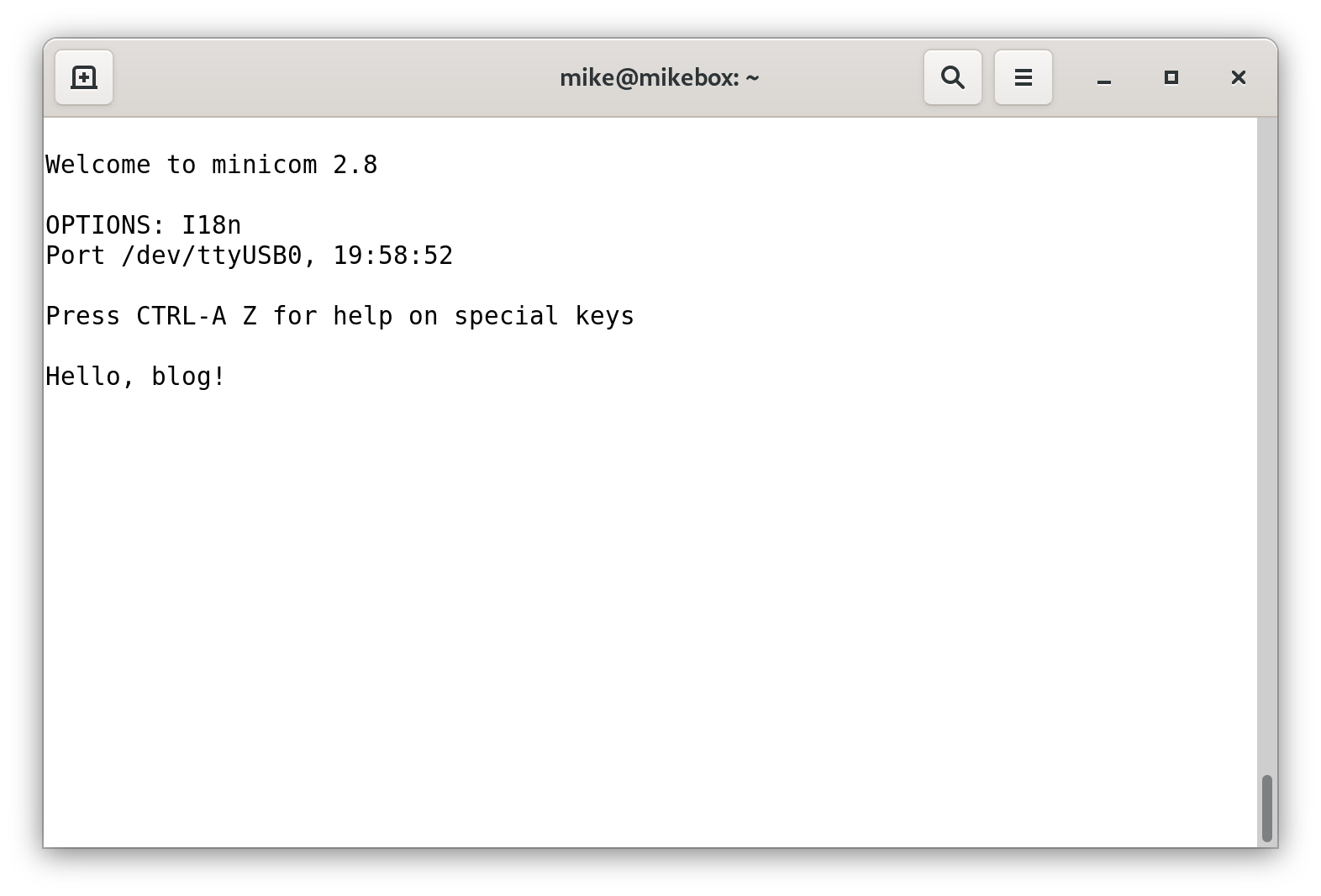
I ended up with a program which prints “Hello” to both the LCD and serial port when the computer resets, then accepts text input. Any characters received over serial are then printed back to the terminal, and also to the LCD.
Mistakes were made
Since this is a learning project, I’m keeping a log of mistakes that I’m making along the way. Today’s lesson is to check everything, because it’s very difficult to debug multiple problems at once. When I ran my first test program, there were four faults.
- I interfaced the USB/UART module to the 65C51 by matching up pin names, which does not work - RX on one side of the serial connection should go to TX on the other.
- I incorrectly calculated the memory map, so the test program was writing to address 8000 while the 65C51 was mapped to address 4000.
- I based my code on examples which do not work on this chip revision, because of the hardware bug noted above.
- I also miscalculated the baud rate, so even if I didn’t have the other faults, my settings for
minicomwould not have worked.
Wrap-up
It’s very straightforward to modify Ben Eater’s 6502 computer design by adding a 65C51 ACIA. This upgrade will allow me to write (or port) software which uses text I/O. I’m planning a few more changes to this design before I port anything too serious though.
This is also the first time I’ve included (pieces of) schematics in a blog post. I’m drawing these with KiCad, and using a slightly modified version of Nicholas Parks Young’s 6502 KiCad library, which has saved me a bit of time.