I am currently working on building a computer based on the 65C816 processor. This processor has a 16-bit stack pointer, which should make it far more capable than the earlier 65C02, at least in theory.
I wanted to check my understanding of how the stack works on this processor, so I tried to build the simplest possible implementation of preemptive multitasking in 65C816 assembly.
What I’m working with
I am working with a breadboard computer. It has no operating system, and no ability to load programs or start/stop processes.
To get code running, I am assembling it on a modern computer, then writing the resulting binary to an EEPROM chip.
To see the result of the code, I am using a logic analyser to watch some output pins on the 65C22 VIA. The 65C22 chip also has a timer, so I connected its interrupt output to the NMI input of the CPU for this test.
Test programs
I wrote two simple programs which infinitely loop. These programs use ca65 assembler syntax.
The 65C22 has two 8-bit ports, so I made each test program write a recognisable pattern to its own output port, so that it’s easy to see which one is running at any given time, and check that it is not disrupted by the task switching.
The first program writes to Port A of the 65C22, and alternates the value between 0000 0000, and 0000 0011.
.segment "CODE"
; Task 1
task_1_main:
  .a8                             ; use 8-bit accumulator and index registers
  .i8
  sep #%00110000
@repeat_1:
  lda #%00000000                  ; alternate between two values
  sta PORTA
  lda #%00000011
  sta PORTA
  jmp @repeat_1                   ; repeat forever
The second program writes to Port B of the 65C22. This uses a ror instruction to produce a pattern across all digits of the output port.
.segment "CODE"
; Task 2
task_2_main:
  .a8                             ; use 8-bit accumulator and index registers
  .i8
  sep #%00110000
  clc
  lda #%01010101                  ; grab a start value
@repeat_2:
  ror                             ; rotate right
  sta PORTB
  jmp @repeat_2                   ; repeat forever
Context switching
I’m implementing round-robin scheduling between two processes.
My basic plan was to use a regular interrupt routine to save context, switch the stack pointer to the other process, restore context for the next process, then return from the interrupt.
.segment "CODE"
nmi:
  .a16
  .i16
  rep #%00110000
  ; Save task context to stack
  pha                             ; Push A, X, Y
  phx
  phy
  phb                             ; Push data bank, direct register
  phd

  ; swap stack pointer so that we will restore the other task
  tsc                             ; transfer current stack pointer to memory
  sta temp
  lda next_task_sp                ; load next stack pointer from memory
  tcs
  lda temp                        ; previous task is up next
  sta next_task_sp

  ; Clear interrut
  .a8
  .i8
  sep #%00110000                  ; save X only (assumes it is 8 bits..)
  ldx T1C_L                       ; Clear the interrupt, side-effect of reading

  .a16
  .i16
  rep #%00110000
  ; Restore process context from stack, reverse order
  pld                             ; Pull direct register, data bank
  plb
  ply                             ; Pull Y, X, A
  plx
  pla
  rti
Setup process
The above switch works while the two processes are up and running, that takes some setting up. Firstly, the two variables need to be referenced somewhere.
.segment "BSS"
next_task_sp: .res 2              ; Stack pointer of whichever task is not currently running
temp: .res 2
The boot-up routine then sets everything up. It’s broken up a bit here. First is the CPU initialisation, since the 65C816 will boot to emulation mode.
.segment "CODE"
reset:
  clc                             ; switch to native mode
  xce
The second step is to start a task in the background. This involves pushing appropriate values to the stack, so that when we context switch, “Task 2” will start executing from the top.
  ; Save context as if we are at task_2_main, so we can switch to it later.
  .a16                            ; use 16-bit accumulator and index registers
  .i16
  rep #%00110000
  lda #$3000                      ; set up stack, direct page at $3000
  tcs
  tcd
  ; emulate what is pushed to the stack before NMI is called: program bank, program counter, processor status register
  phk                             ; program bank register, same as current code, will be 0 here.
  pea task_2_main                 ; 16 bit program counter for the start of this task
  php                             ; processor status register
  ; match what we push to the stack in the nmi routine
  lda #0
  tax
  tay
  pha                             ; Push A, X, Y
  phx
  phy
  phb                             ; Push data bank, direct register
  phd
  tsc                             ; save stack pointer to next_task_sp
  sta next_task_sp

  lda #$2000                      ; set up stack, direct page at $2000 for task_1_main
  tcs
  tcd
The nex step is to set up a timer, so that the interrupt routine will fire regularly. This causes interrupts to occur ~28 times per second.
  ; Set up the interrupt timer
  .a8                             ; use 8-bit accumulator and index registers
  .i8
  sep #%00110000
  lda #%11111111                  ; set all VIA pins to output
  sta DDRA
  sta DDRB
  ; set up timer 1
  lda #%01000000                  ; set ACR. first two bits = 01 is continuous interrupts for T1
  sta ACR
  lda #%11000000                  ; enable VIA interrupt for T1
  sta IER
  ; set up a timer at ~65535 clock pulses.
  lda #$ff                        ; set T1 low-order counter
  sta T1C_L
  lda #$ff                        ; set T1 high-order counter
  sta T1C_H
Finally, “Task 1” can be started in the foreground.
  ; start running task 1
  jmp task_1_main
Linker configuration and boilerplate
This is the first time I’m blogging about code written in 65C816 native mode, so for the sake of completeness, I’ll also include the updated linker configuration. The most important change (compared with this blog post) to that 32 bytes are now set aside for interrupt vectors.
MEMORY {
    ZP:     start = $00,    size = $0100, type = rw, file = "";
    RAM:    start = $0100,  size = $7e00, type = rw, file = "";
    PRG:    start = $e000,  size = $2000, type = ro, file = %O, fill = yes, fillval = $00;
}

SEGMENTS {
    ZEROPAGE: load = ZP,  type = zp;
    BSS:      load = RAM, type = bss;
    CODE:     load = PRG, type = ro,  start = $e000;
    VECTORS:  load = PRG, type = ro,  start = $ffe0;
}
Note that this linker configuration is not quite complete, but it is good enough to get code running. The zero page is not relevant for the code I’ll be writing, so I might remove that at some point.
I also have definitions for the 65C22 I/O registers, which correspond to the location that it is mapped into RAM on my prototype computer.
PORTB = $c000
PORTA = $c001
DDRB = $c002
DDRA = $c003
T1C_L = $c004
T1C_H = $c005
ACR = $c00b
IFR = $c00b
IER = $c00e
The final piece of the puzzle then, are definitions for all those interrupt vectors.
.segment "CODE"
irq:
  rti

unused_interrupt:                 ; Probably make this into a crash.
  rti

.segment "VECTORS"
; native mode interrupt vectors
.word unused_interrupt            ; Reserved
.word unused_interrupt            ; Reserved
.word unused_interrupt            ; COP
.word unused_interrupt            ; BRK
.word unused_interrupt            ; Abort
.word nmi                         ; NMI
.word unused_interrupt            ; Reserved
.word irq                         ; IRQ

; emulation mode interrupt vectors
.word unused_interrupt            ; Reserved
.word unused_interrupt            ; Reserved
.word unused_interrupt            ; COP
.word unused_interrupt            ; Reserved
.word unused_interrupt            ; Abort
.word unused_interrupt            ; NMI
.word reset                       ; Reset
.word unused_interrupt            ; IRQ/BRK
The process for building this assembly code into a usable ROM are:
ca65 --cpu 65816 main.s
ld65 -o rom.bin -C system.cfg main.o
This outputs an 8KiB file. I need to pad this with zeroes up to 32KiB, which is the size of the ROM chip I am burning it to.
truncate -s 32768 rom.bin
Lastly, I write this to the ROM.
minipro -p AT28C256 -w rom.bin
Result
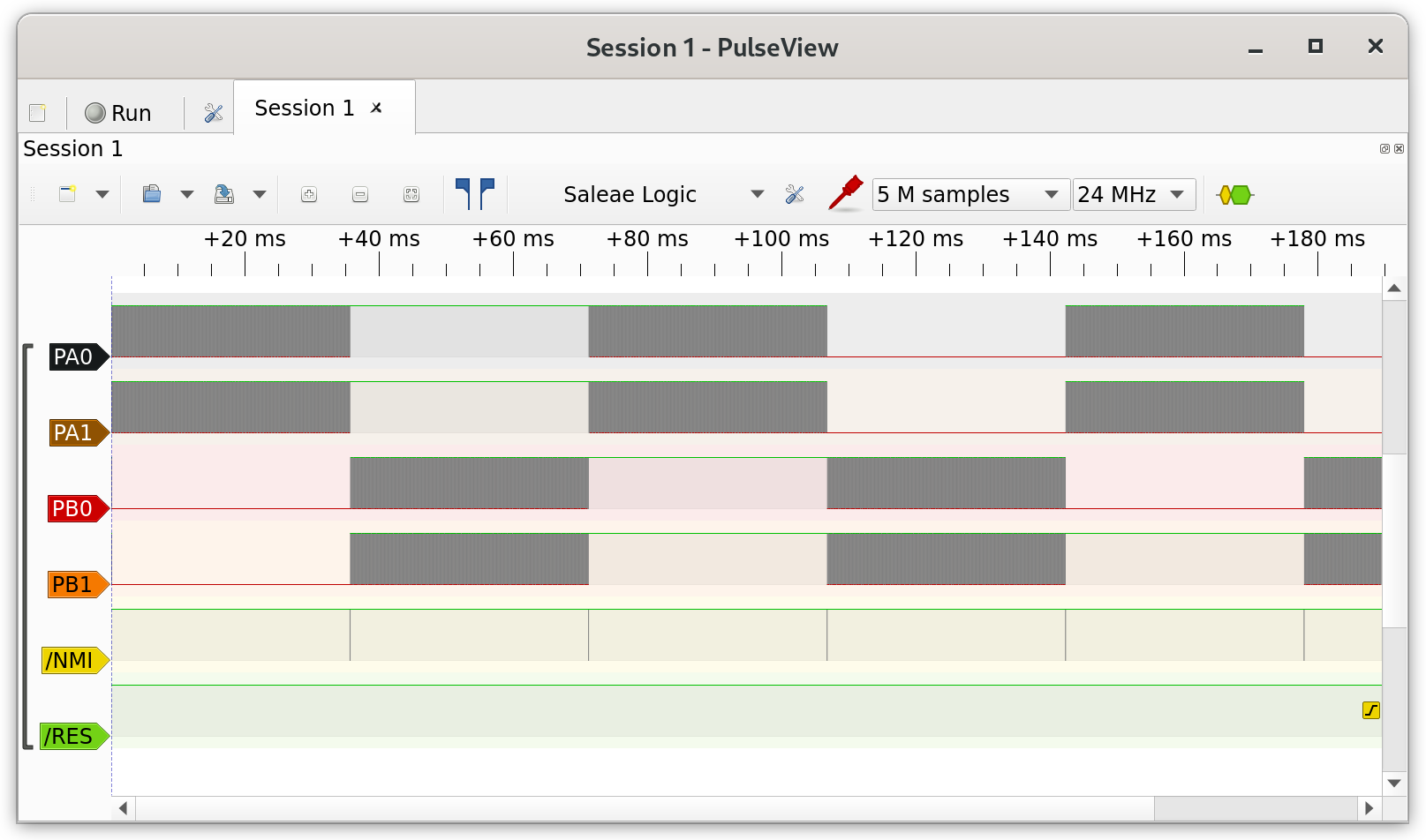
I connected a logic analyser to two wires from each output port, the NMI interrupt line, and the reset signal, and opened up sigrok.
This clearly shows the CPU switching between the two processes each time an interrupt is triggered.
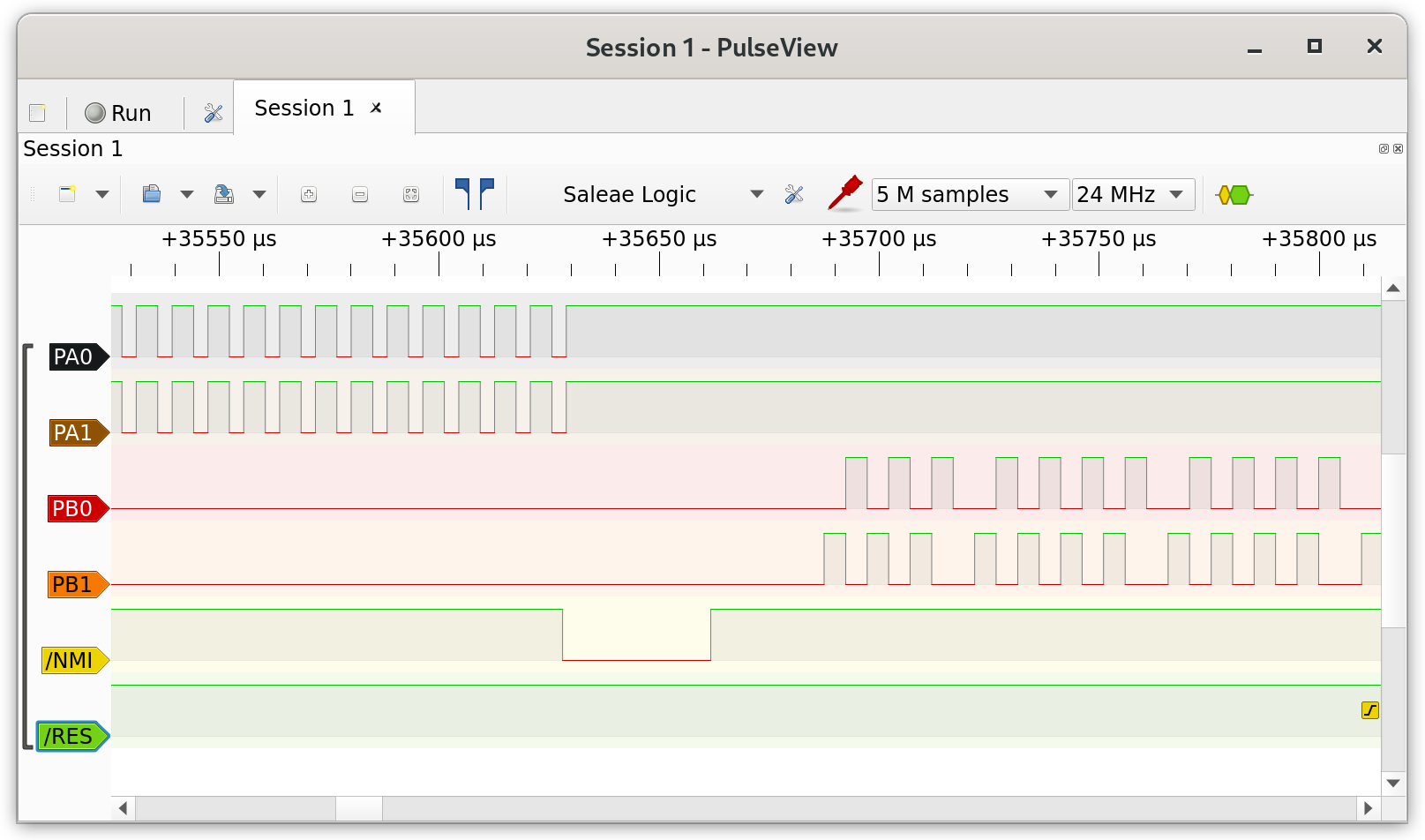
Zooming in on the task cut-over, I can also see that the patterns on each port are different, as expected.
Of course this did not work the first time, and I spent quite a bit of time de-constructing and re-constructing the code to isolate bugs.
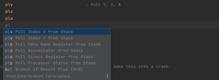
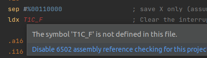
As result, I shipped some improvements to my 6502 assembly plugin for JetBrains IDE’s, which I have blogged about previously. The plugin will now provide suggestions for mnemonics. There is a project setting for 6502 vs 65C02 vs 65C816 mode, and it will only suggest mnemonics which are available for the CPU.
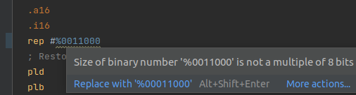
It also provides a weak warning for binary or hex numbers which are not 8, 16 or 24 bits, which would have saved me some time.
Lastly, it has optional checking for undefined/unused values. This helps catch problems in the editor, and allows me to identify unused code and variables.
Wrap-up
I already knew how multitasking works on a high-level, but it was quite interesting to implement it myself. I have been using this as a test program for my 65C816 computer, since it exercises RAM, ROM, I/O, and uses interrupts.
I don’t think I will be able to use this exact method for more complex programs, because it will break down a bit with multiple interrupt sources. After writing this code, I also found that it’s not common for modern systems to save register values to the stack when context-switching, and that a process control block is used instead.
The next step for my 65C816 computer will be the addition of an NXP UART, which I tested in an earlier blog post.