I’ve recently been learning a bit about how computers work on a low-level by building a 6502-based retro computer from scratch. I’ve noticed that plenty of retro computer designs use simple programmable logic devices, including GAL’s, PAL’s and PLA’s.
I decided to take a closer look at these, since they may be a useful part of my toolkit. The particular part which grabbed my attention was the ATF22V10 programmable logic device (PLD).
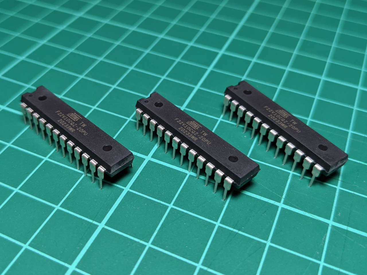
This ticks a few important boxes for my current projects:
- Available in DIP packaging, so it is suitable for use on a breadboard.
- Operates at 5 volts.
- Currently in production.
- Has a relatively high pin count (slightly more than the ATF16V8).
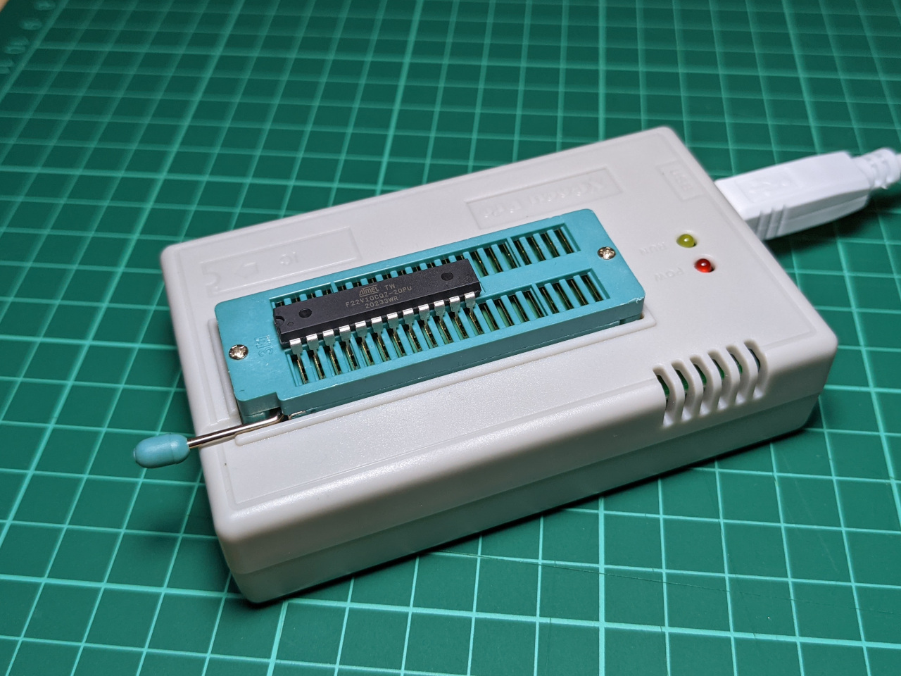
- Can be programmed using a TL866II+ programmer, which I already use for EEPROM programming.
These devices have been around for many decades, and I found mixed information online about the software and hardware requirements for programming these chips. A lot more has been written about the (discontinued) Lattice 22V10, which has similar capabilities, but a different programming process.
Setting up a programming environment
The logic functions for programming the ATF22V10 are specified using a human-readable hardware description language, which needs to be compiled into a device-specific “fuse map” for programming the device.
The only real choice for the ATF22V10 seems to be an obscure language called CUPL, which can be processed by Atmel/Microchip’s proprietary compiler, WinCUPL. This is distributed as a freeware Windows binary, downloadable from this page on the Microchip website.
I do all of my other software development on Linux, so I installed WinCUPL in a WINE environment. On Ubuntu 20.04, WINE is installed with the following command:
sudo apt-get install wine
For later parts of the process, I found that I also needed winetricks and cabextract:
sudo apt-get install cabextract
wget https://raw.githubusercontent.com/Winetricks/winetricks/master/src/winetricks
chmod +x winetricks
The install was simple:
wine awincupl.exe
I was then launching the program with the following command.
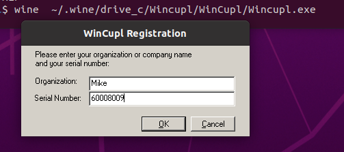
$ wine ~/.wine/drive_c/Wincupl/WinCupl/Wincupl.exe
On first start-up, it prompted for registration info. This is a carry-over from before this tool was freeware, and the download page lists the correct key as 60008009.
I got persistent errors about missing DLL modules.
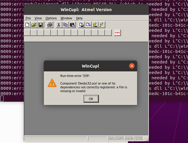
I initially thought that this was a library registration or 32/64-bit compatibility issue, though I eventually found that I needed to install mfc40 via winetrics:
$ ./winetricks mfc40
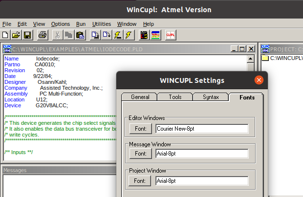
After this installer ran, I was able to launch WinCUPL. The editor was using a a proportional font, though the dialog indicated that it was attempting to use Courier New, which is monospace.
This is fixed by installing the Microsoft fonts via the ttf-mscorefonts-installer package.
sudo apt-get --reinstall install ttf-mscorefonts-installer
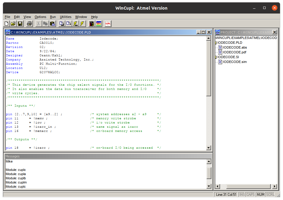
At this point I had a working editor. If it was not clear yet that this is ancient technology, this screen capture shows the I/O decoding example which is bundled with WinCUPL, which was apparently written in 1984.
Writing a test program
WinCUPL ships with a folder of example programs, and some documentation which includes a reference manual and tutorial. Most introductory information online seems to be from old electrical or computer engineering courses.
I read through:
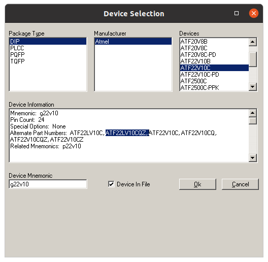
The closest thing to a “Hello World” program for one of these chips is the GATES.PLD example, which shows how to apply some basic logic operations. It was written for the ATF16V8, so I looked up my own device to find its mnemonic, g22v10:
After swapping around the pins, I ended up with this program for testing the ATF22V10:
Name     MyTest;
PartNo   00;
Date     6/07/2021;
Revision 01;
Designer Mike;
Company  None;
Assembly None;
Location None;
Device   g22v10;

Pin 1 = a;
Pin 2 = b;

Pin 14 = inva;
Pin 15 = invb;
Pin 16 = and;
Pin 17 = nand;
Pin 18 = or;
Pin 19 = nor;
Pin 20 = xor;
Pin 21 = xnor;

inva = !a;
invb = !b;
and = a & b;
nand = !(a & b);
or = a # b;
nor = !(a # b);
xor = a $ b;
xnor = !(a $ b);
To get a JED file from this, I navigated to compile options, and disabled the “Simulate” and “Absolute” options. This skips the simulation step, which otherwise blocks compilation.
I did not find the simulator very intuitive, but I did return to it later after watching this recent tutorial. The devices can only be reprogrammed 100 times, so for anything complex, I’ll definitely be checking outputs in the simulator rather than relying on trial-and-error.
Programming the chip
I use TL866II+ programmer with the minipro open source programming software for other chips, and I found mixed information online about whether this would work for the ATF22V10.
In my case, it worked, but only after a few attempts. My first mistake was to read the chip instead of writing it.
$ minipro -p ATF22V10CQZ -r MyTest.jed
Found TL866II+ 04.2.86 (0x256)
Warning: Firmware is out of date.
  Expected  04.2.123 (0x27b)
  Found     04.2.86 (0x256)
Reading device...  0.54Sec  OK
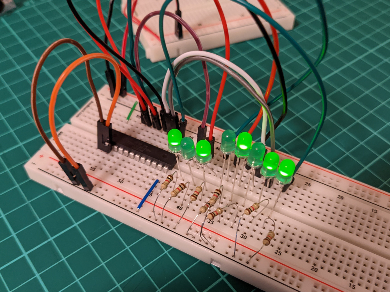
When I plugged this into my test circuit (shown later), the blank chip warmed up, and produced erratic output.
After re-generating the JED file, I programmed the chip again, but got some warnings and verification errors. The chip still produced heat and erratic output in my test circuit.
$ minipro -p ATF22V10CQZ -w MyTest.jed
Found TL866II+ 04.2.86 (0x256)
Warning: Firmware is out of date.
  Expected  04.2.123 (0x27b)
  Found     04.2.86 (0x256)

VPP=12V
Warning! JED file doesn't match the selected device!

Declared fuse checksum: 0x7005 Calculated: 0x7005 ... OK
Declared file checksum: 0x6DDD Calculated: 0x6DDD ... OK
JED file parsed OK

Use -P to skip write protect

Erasing... 0.82Sec OK
Writing jedec file...  4.97Sec  OK
Reading device...  0.54Sec  OK
Writing lock bit... 0.26Sec OK
Verification failed at address 0x0006: File=0x00, Device=0x01
Reading back the device produced a completely different JED file (different length, different contents).
Detour: Firmware update
I started digging into the warnings, and decided to attempt a firmware update. The best instructions I could find for this were from this GitLab issue.
The short version is that once you have a firmware file from the hardware vendor, they can be applied by minipro.
$ minipro -F updateII.dat
Found TL866II+ 04.2.86 (0x256)
Warning: Firmware is out of date.
  Expected  04.2.123 (0x27b)
  Found     04.2.86 (0x256)
updateII.dat contains firmware version 4.2.126 (newer)

Do you want to continue with firmware update? y/n:y
Switching to bootloader... failed!
I got this error, probably because the device was restarted. On my setup, I am passing the USB device through to a VM, and needed to press a button to redirect it again.
$ minipro -F updateII.dat
Found TL866II+ in bootloader mode!
updateII.dat contains firmware version 4.2.126 (newer)

Do you want to continue with firmware update? y/n:y
Erasing... OK
Reflashing... 100%
Resetting device... OK
Reflash... OK
Programming the chip again
With the updated firmware, I made a third attempt to write the chip, using the same JED file as before.
$ minipro -p ATF22V10CQZ -w MyTest.jed
Found TL866II+ 04.2.126 (0x27e)
Warning: Firmware is newer than expected.
  Expected  04.2.123 (0x27b)
  Found     04.2.126 (0x27e)

VPP=12V
Warning! JED file doesn't match the selected device!

Declared fuse checksum: 0x7005 Calculated: 0x7005 ... OK
Declared file checksum: 0x6DDD Calculated: 0x6DDD ... OK
JED file parsed OK

Use -P to skip write protect

Erasing... 0.33Sec OK
Writing jedec file...  5.04Sec  OK
Reading device...  0.41Sec  OK
Writing lock bit... 0.35Sec OK
Verification failed at address 0x16C6: File=0x01, Device=0x00
Reading the device returned a JED file with all 0’s, and there are still some warnings, but the circuit appeared to work correctly.
Alternatives
The firmware update seemed to fix any problems for me, but I have read plenty of accounts of tricky issues when attempting to program the ATF22V10 with the TL866II+ programmer.
An alternative programmer might be the Wellon VP-290 (mentioned here). On the software side, using the ATF22V10 really seems to require WinCUPL, though it does have a command-line.
There is plenty of software designed for the discontinued Lattice 22V10 GAL, though my best guess is that these are not compatible with the Atmel chips I’m using here. These include GALasm, which has a license which prohibits commercial use (enough for me to steer clear), plus an open source re-implementation called galette.
Wrap-up
It’s been interesting to take a look at the lowest-possible level of the software stack, even just to produce a “Hello World” program.
I am not using PLD’s in my current project, but it’s good to know that I could program one if I needed to. The main use for me would be as an alternative to discrete logic chips, so that I can keep parts count, layout space, and propagation delays under control. For prototyping, it will also be helpful to be able to replicate old circuits which use similar components, or to simulate logic chips which aren’t in my inventory.
One thing that I learned is that a fuse is not the same as a gate. The device I used has thousands of fuses (programmable connections) which are capable of configuring the inputs to a few hundred gates. If the temperature of my first two programming attempts is anything to go by, it seems to be perfectly possible to configure the fuses to produce a short circuit.