I recently built a small 6502-based computer on a custom PCB, which I designed in KiCad. This blog post is about the process of building a 3D-printed case to house this project, using Blender.
This is my first ever 3D print, so I had a few things to learn.
Quick background
My effort on this project has been focused on making a design which works, then transferring that design to a PCB. Since this is my first electronics project, I’m working sequentially, and have completely ignored the need for a case until now.
I could have saved some time if I positioned the ports and mounting holes to match pre-made electronics enclosures, but I’ll take that as a lesson for my next project.
The requirements for the enclosure are simple:
- Ability to mount the PCB inside the case
- Cut-out for power input
- Cut-outs for cable routing to expansion ports
- Cut-outs for power and reset buttons
My PCB design files are in KiCad, and I decided to design the case in Blender, since I already know how to use it. Blender is not a CAD tool, but it is excellent for general-purpose 3D work, and will do just fine for this task.
Getting scale
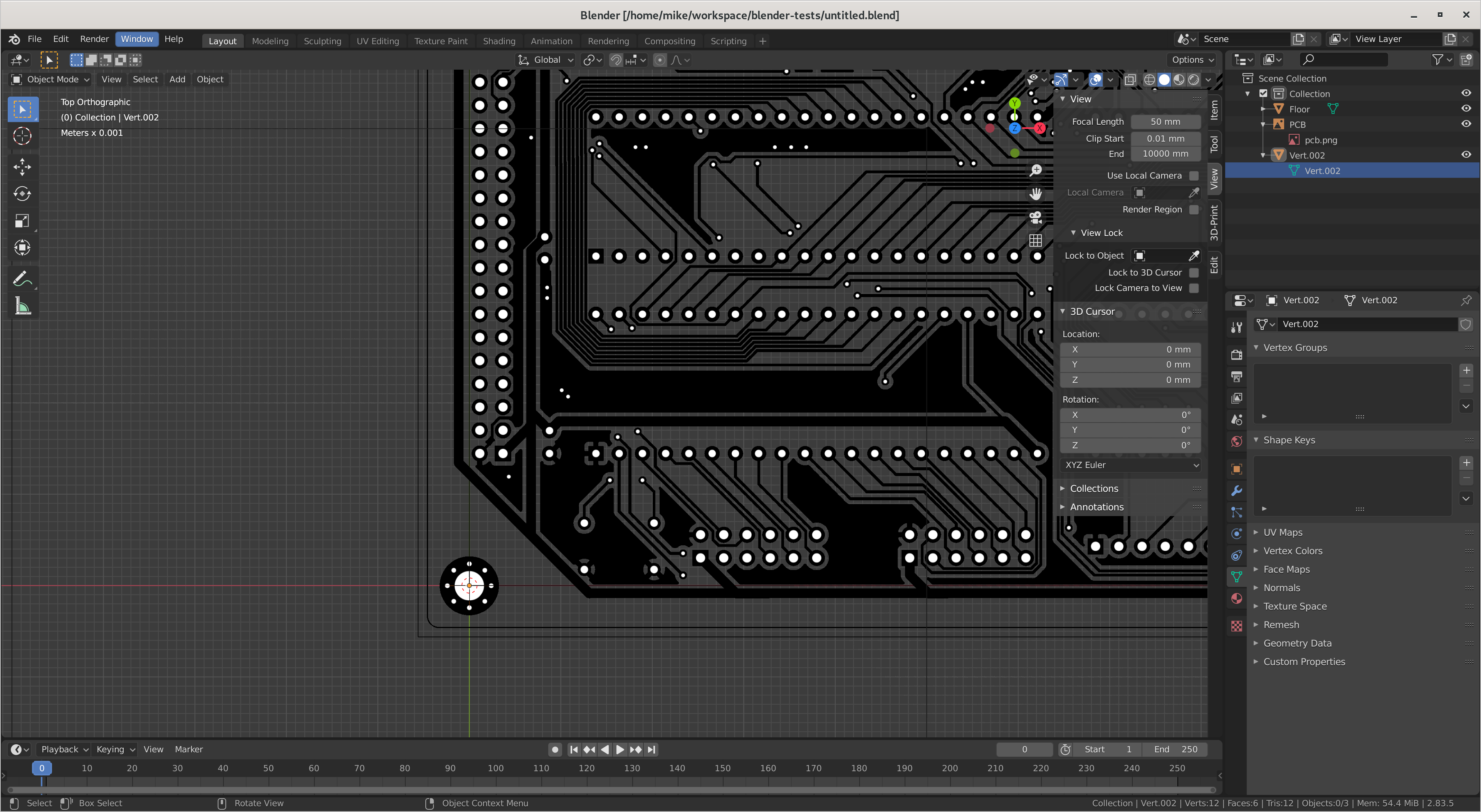
My first challenge was to get the PCB into Blender at the correct scale, so that I could build a model around it. This is mostly just juggling file formats, but also note that Blender works in metres by default. I’ve set it to millimetres, with a scale of 0.001. There are guides on the web about how to set this.
I tried two different methods.
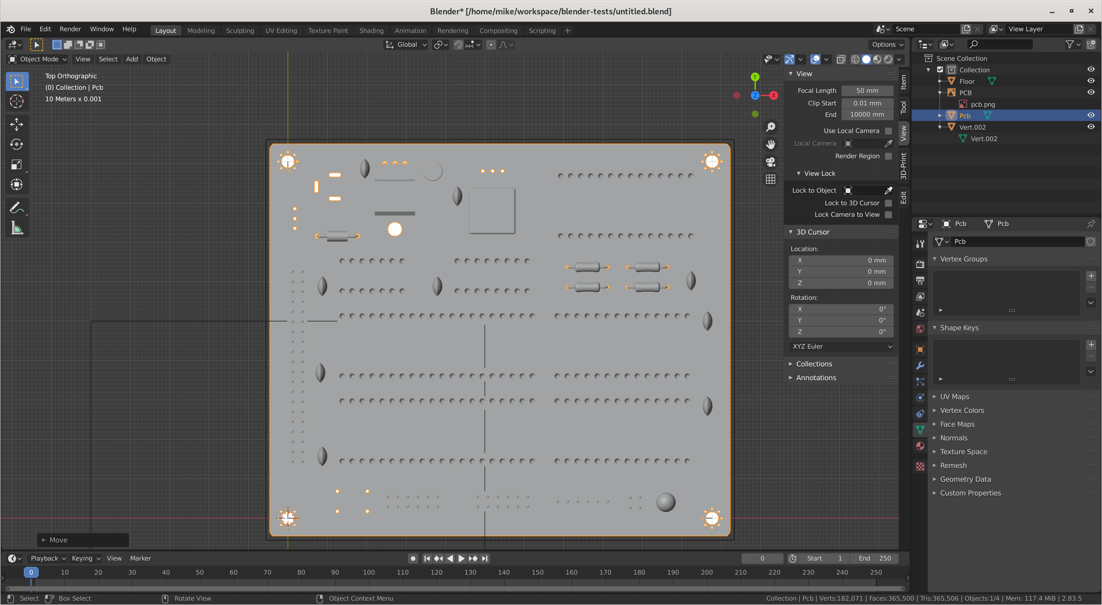
Method 1: Image import
In KiCad, I added two “dimensions” to show the distance between the centre of the mounting holes, then plotted the front copper layer as an SVG.
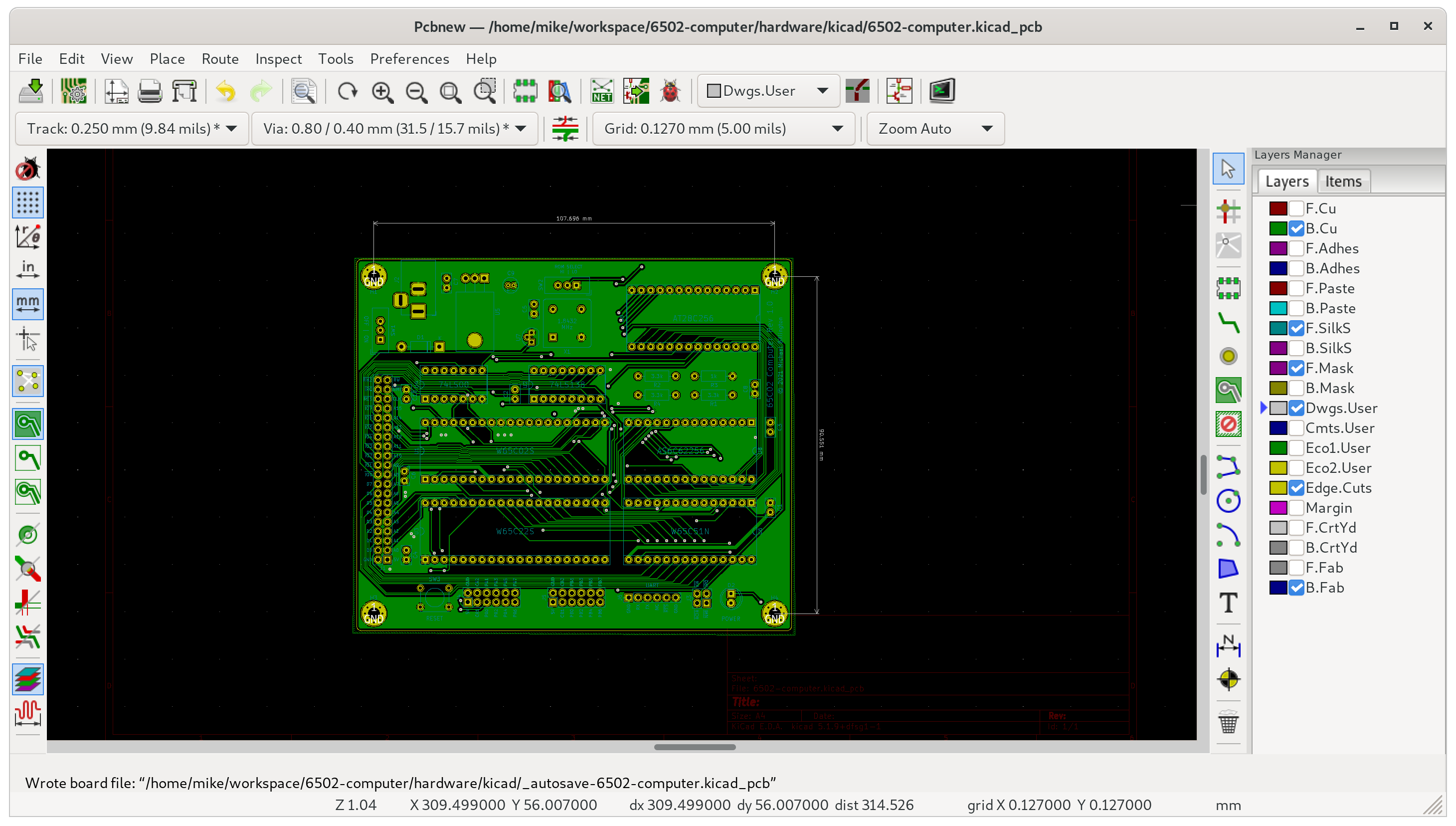
I used Inkscape to convert from SVG to PNG. I then used GIMP to add cross-hairs to the centre of the mounting holes.
In Blender, I added a single vertex at the origin, then extruded it on the X axis to match the measured dimension. I then added a reference image (the PNG file exported above), and scaled/moved the reference image until the cross-hairs lined up with the vertex.
Method 2: Model import
KiCad can export its 3D model to a STEP file. I imported this file into FreeCAD, then exported it to STL.
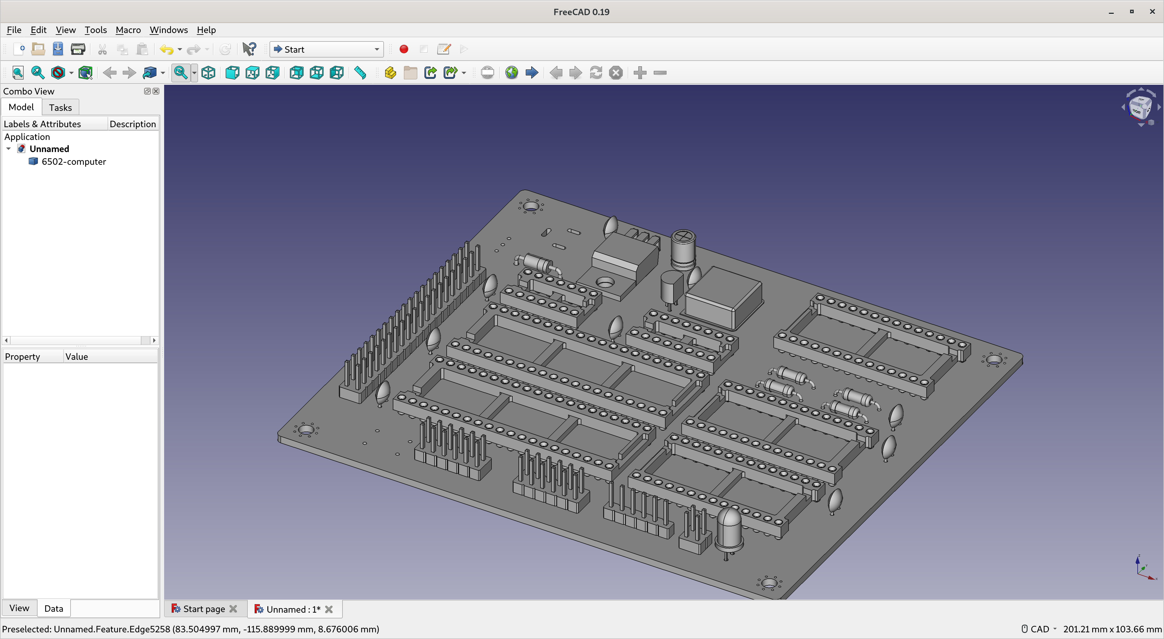
Lastly, I imported the STL into Blender.
The scale is correct with both of these methods, because I can align the image and model.
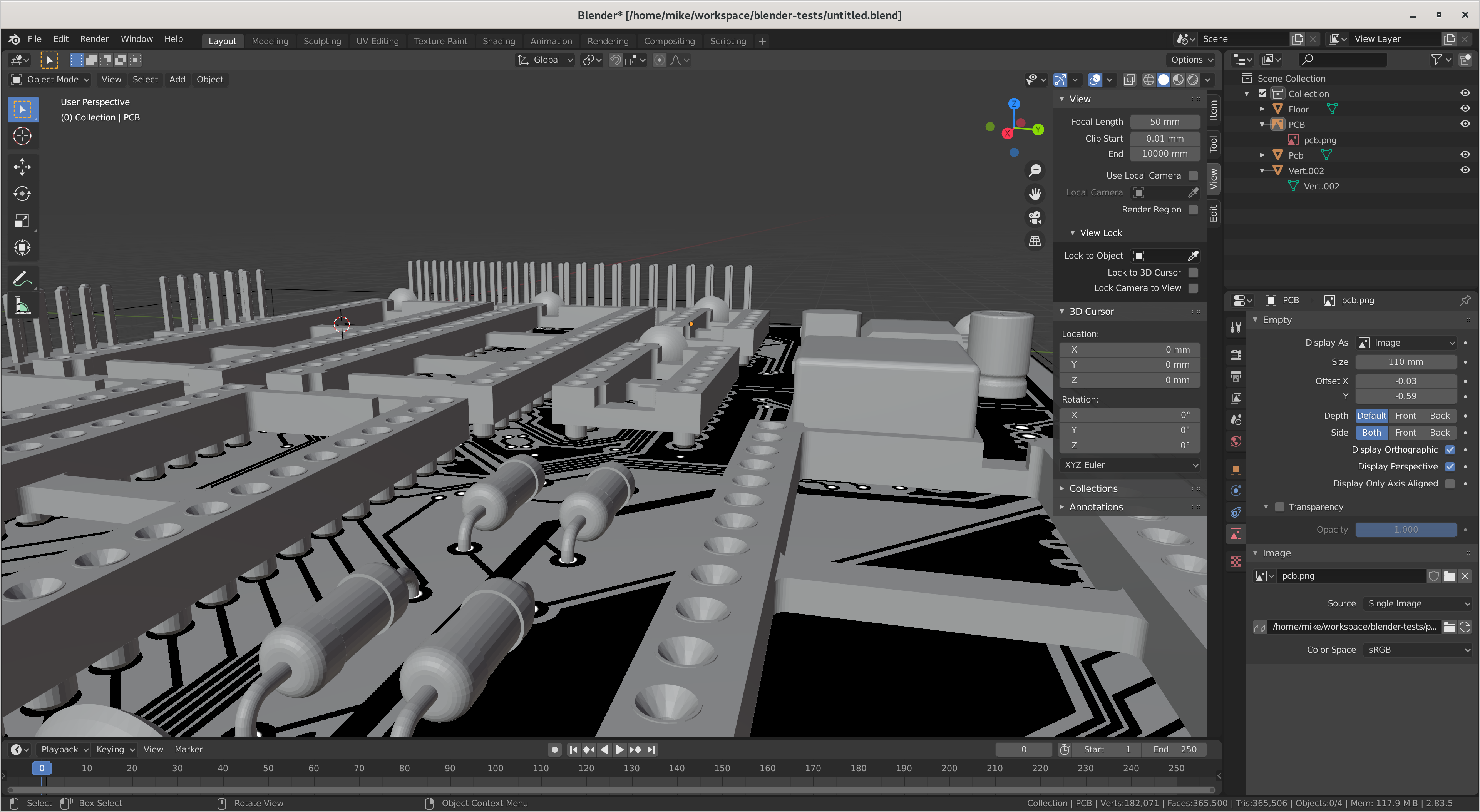
The second method produces much larger .blend files, but has less room to make undetected errors, so I’ll be using it in the future.
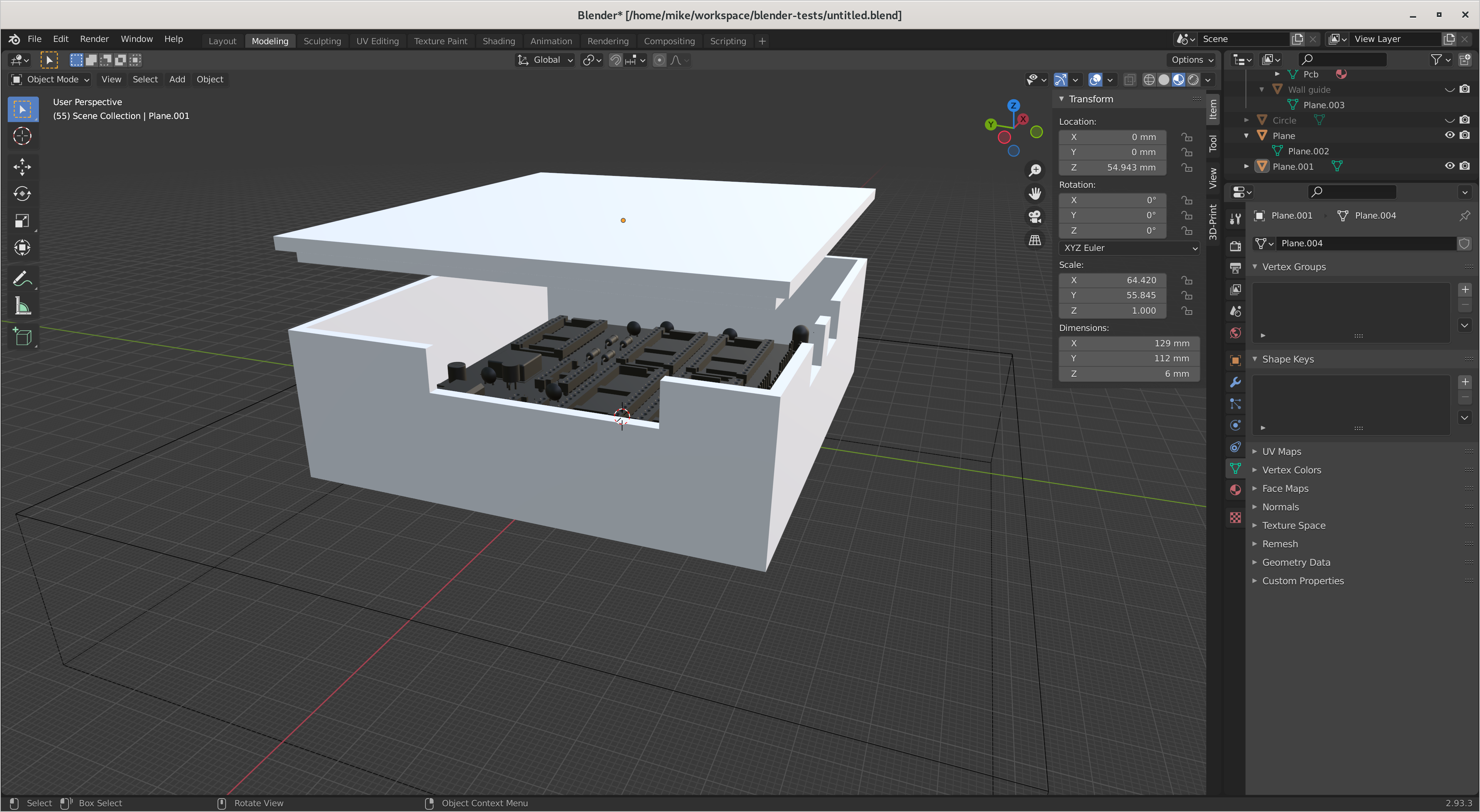
Building a box
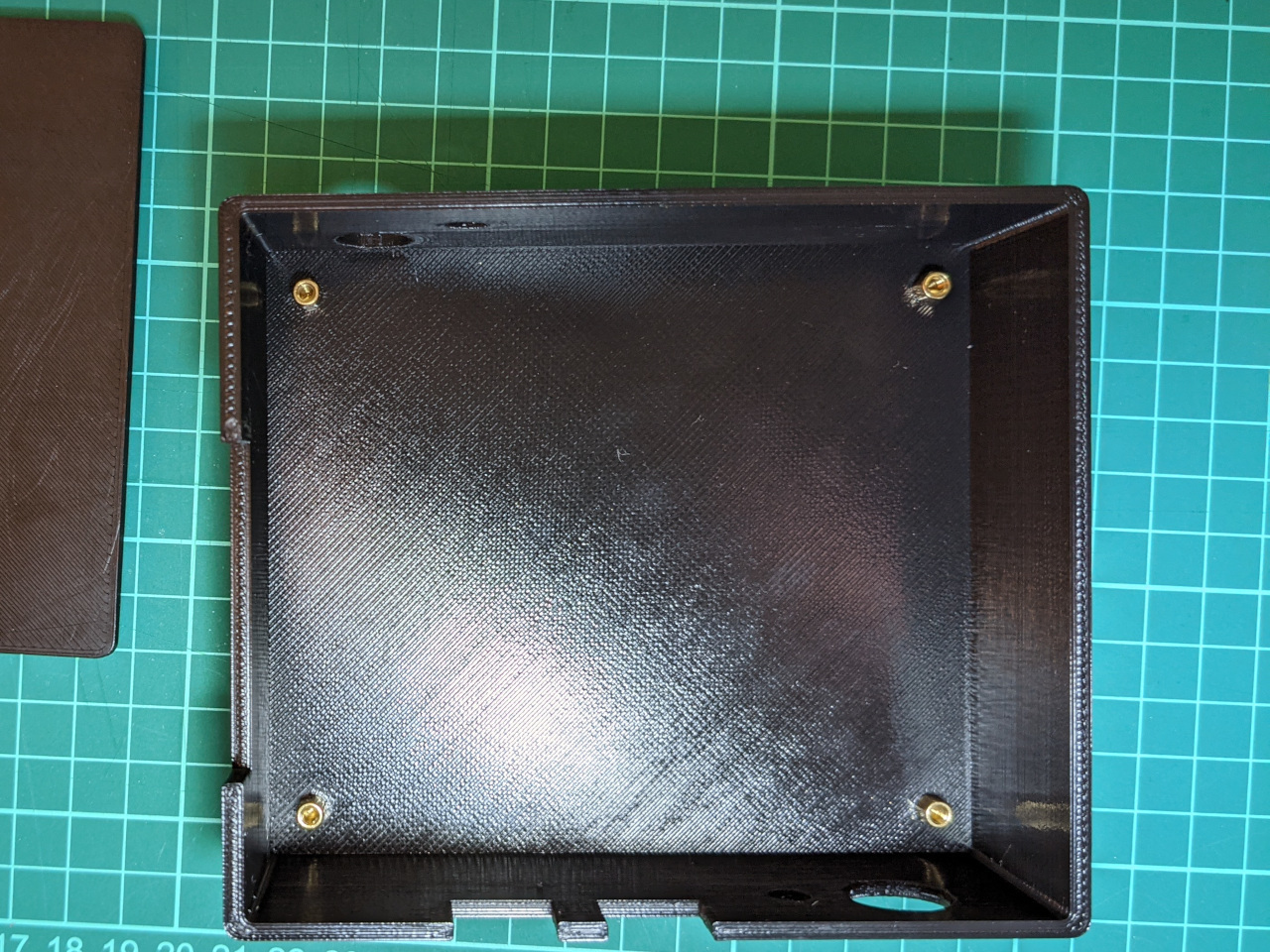
I modeled out the case as a lid and base with 3mm walls, and used boolean modifiers to cut out spaces for buttons and cables.
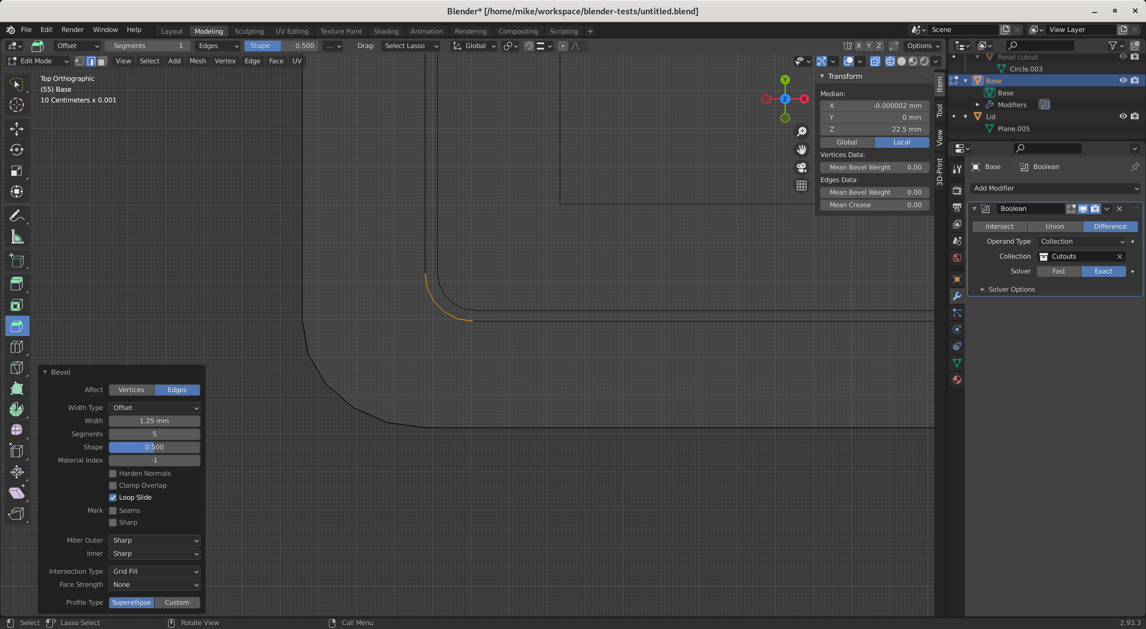
One challenge was rounding the corners without the two pieces intersecting. I built the box as a square, then beveled it in wire-frame view. The spaces are larger than necessary, and I will try using modifiers slot the pieces together with a fixed tolerance if I need to do this again.
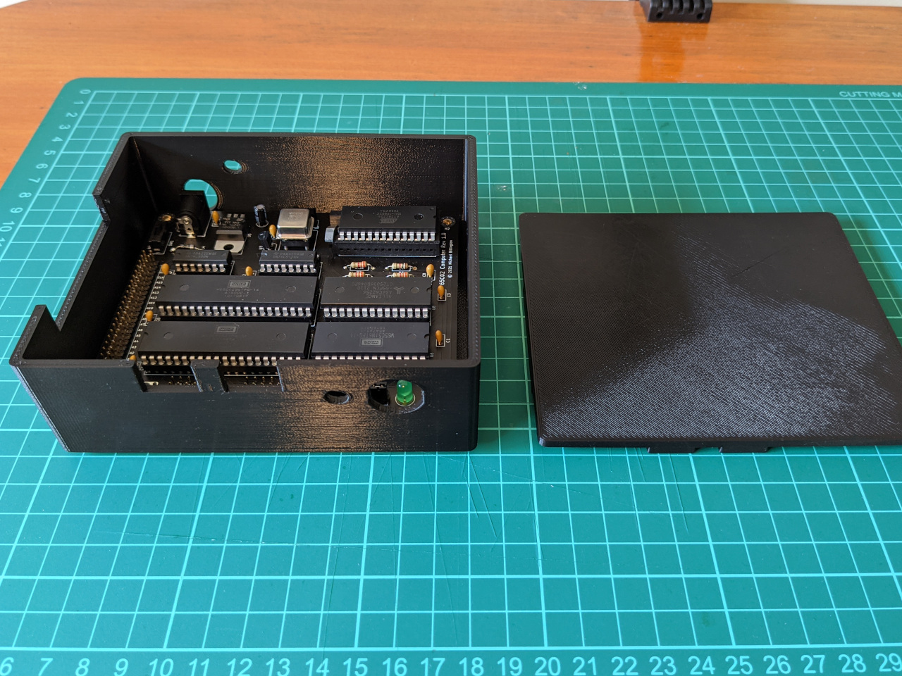
The result was two pieces which sit together but do not attach, with rounded corners and no sharp overhangs, for ease of manufacturing.
Manufacturing and test
I exported the STL files, and sent them to a local manufacturer, since I don’t have my own 3D printer. The print is black PLA, printed with fused deposition modeling, with an 0.2mm layer height and 30% infill.
When I received the parts, I first checked that the two pieces fitted together, then placed a blank PCB over the base to check that the holes lined up. PLA shrinks as it cools, but this aligned perfectly, which is either good luck or correct calibration.
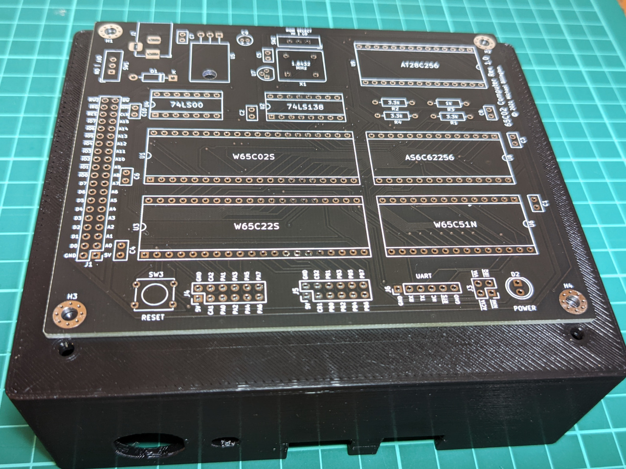
The computer’s board will be installed on standoffs, which are secured by a nut on the other side. I like the idea of using heat-set inserts instead, but I don’t want to try too many new things at once, so I’ve skipped the idea for now.
Next steps
At the time of writing, I’m still waiting for some parts to assemble this computer with a power/reset button, which will be the end of the hardware side of this project.
I’m quite happy with how this turned out as my first ever 3D print. If I need to make enclosures for future projects, I’ll take another look at open source parametric CAD tools such as OpenSCAD and FreeCAD, which are more targeted to this kind of work.
The STL files for this case are available on GitHub at mike42/6502-computer, critique is welcome.