I’ve recently been adding simple hardware devices to my home-built 6502 computer, and ran into a problem.
The 6502 has two active-low interrupt inputs (IRQ and NMI), both of which are used in my design. If I add any devices which can trigger their own interrupts, I will need a way to combine multiple interrupt signals into one.
Choosing an approach
I researched some retro computer designs to see how this problem was handled, and found some very simple approaches.
Most commonly, multiple I/O chips would be connected to the 6502’s IRQ line, which is level-triggered and active-low. As long as all connected chips had an open-drain IRQ output, they could be connected in a so-called wired-or configuration:
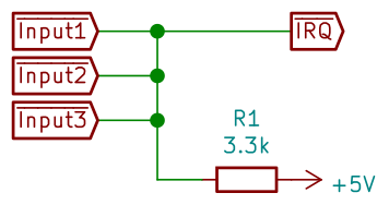
In software, each interrupt source would be checked in priority order.
I can’t use something so straightforward to add hardware to my design, for two main reasons:
- I would need to use logic gates to combine the inputs instead. The I/O chip which is connected to the CPU’s IRQ input at the moment is a WDC 65C22S, which does not have an open-drain IRQ output.
- It’s not going to be practical to check every I/O device from an interrupt service routine. I’m planning to add devices which are accessed over SPI, and will take many clock cycles to return their status.
Over in the PC world, programmable interrupt controllers such as the Intel 8259 were used. Among other features, these chips combine multiple interrupt sources into one, and can report the interrupt source on the data bus.
Rather than use out-of-production retro parts, I decided to program an ATF22V10 programmable logic device with these functions. A PLD is cheaper, and I’ve just figured out how to program them, so I might as well put those skills to use.
Creating the interrupt controller
I am using galette to program these PLD’s, and went through 5 revisions of the PLD source file before landing on something which could complete these functions.
- combine multiple interrupt lines into one.
- allow the CPU to quickly identify the highest-priority interrupt to service.
For this section, I’ll briefly describe each part of the PLD definition is doing.
The file starts with the name of the target device, and a name for the chip.
GAL22V10
IrqController
Next pin definitions are listed. I’m using the ATF22V10, which has 24 pins. The first row is pins 1-12, while the second row is pins 13-24. Numbers go left-to-right in both rows, unlike a physical microchip!
Clock    /IRQ0 /IRQ1 IRQ2  /IRQ3 /IRQ4 IRQ5  /IRQ6 /IRQ7 /IRQ8 /IRQ9  GND
/CS      D7    D6    D5    D4    D3    D2    D1    D0    /IRQ  /WE    VCC
For combining the interrupts, I simply use a big OR function.
IRQ = IRQ0 + IRQ1 + IRQ2 + IRQ3 + IRQ4 + IRQ5 + IRQ6 + IRQ7 + IRQ8 + IRQ9
This reads “IRQ is active if IRQ0 is active or IRQ1 is active or IRQ2 is active, etc.”. All logic is the positive case, so “IRQ0” means “IRQ0 is active”. Whether “active” means 1 or 0 at the input depends on those pin definitions. The active-low inputs are inverted before being fed to this expression, and the result will be inverted if the output is active-low. This confused me at first, because I thought that “/IRQ0” is just a pin name.
The expressions for the data bus come next.
- These are all ‘registered’ outputs (indicated with the
.Rsuffix). This runs the output through a D-type flip-flop, so that it will only change on clock transitions, rather than asynchronously. This is to avoid garbage output if an interrupt triggers while we are reading from the controller. D1..D4is a priority encoder, encoding the number 0 to 10 to identify the lowest-numbered interrupt source, or 11 if there is no interrupt.- D0 is always 0. This multiples the output by 2, which makes things easier for the software.
D0.R = GND
D1.R = IRQ1*/IRQ0 + IRQ3*/IRQ2*/IRQ1*/IRQ0 + IRQ5*/IRQ4*/IRQ3*/IRQ2*/IRQ1*/IRQ0 + IRQ7*/IRQ6*/IRQ5*/IRQ4*/IRQ3*/IRQ2*/IRQ1*/IRQ0 + IRQ9*/IRQ8*/IRQ7*/IRQ6*/IRQ5*/IRQ4*/IRQ3*/IRQ2*/IRQ1*/IRQ0
D2.R = IRQ2*/IRQ1*/IRQ0 + IRQ3*/IRQ2*/IRQ1*/IRQ0 + IRQ6*/IRQ5*/IRQ4*/IRQ3*/IRQ2*/IRQ1*/IRQ0 + IRQ7*/IRQ6*/IRQ5*/IRQ4*/IRQ3*/IRQ2*/IRQ1*/IRQ0 + /IRQ9*/IRQ8*/IRQ7*/IRQ6*/IRQ5*/IRQ4*/IRQ3*/IRQ2*/IRQ1*/IRQ0
D3.R = IRQ4*/IRQ3*/IRQ2*/IRQ1*/IRQ0 + IRQ5*/IRQ4*/IRQ3*/IRQ2*/IRQ1*/IRQ0 + IRQ6*/IRQ5*/IRQ4*/IRQ3*/IRQ2*/IRQ1*/IRQ0 + IRQ7*/IRQ6*/IRQ5*/IRQ4*/IRQ3*/IRQ2*/IRQ1*/IRQ0
D4.R = /IRQ7*/IRQ6*/IRQ5*/IRQ4*/IRQ3*/IRQ2*/IRQ1*/IRQ0
D5.R = GND
D6.R = GND
D7.R = GND
For the 22V10, not all pins support the same number of product terms. As I built up to 10 interrupt sources, I needed to re-arrange the pins a few times.
Lastly, I needed to tri-state the output when the chip was not being read. This is a second definition for each pin (.E suffix). I used both a chip select (/CS) and write enable (/WE) input. The interrupt controller cannot be written to, this just allows me to avoid bus contention if somebody is attempting to.
D0.E = CS*/WE
D1.E = CS*/WE
D2.E = CS*/WE
D3.E = CS*/WE
D4.E = CS*/WE
D5.E = CS*/WE
D6.E = CS*/WE
D7.E = CS*/WE
Test circuit and software
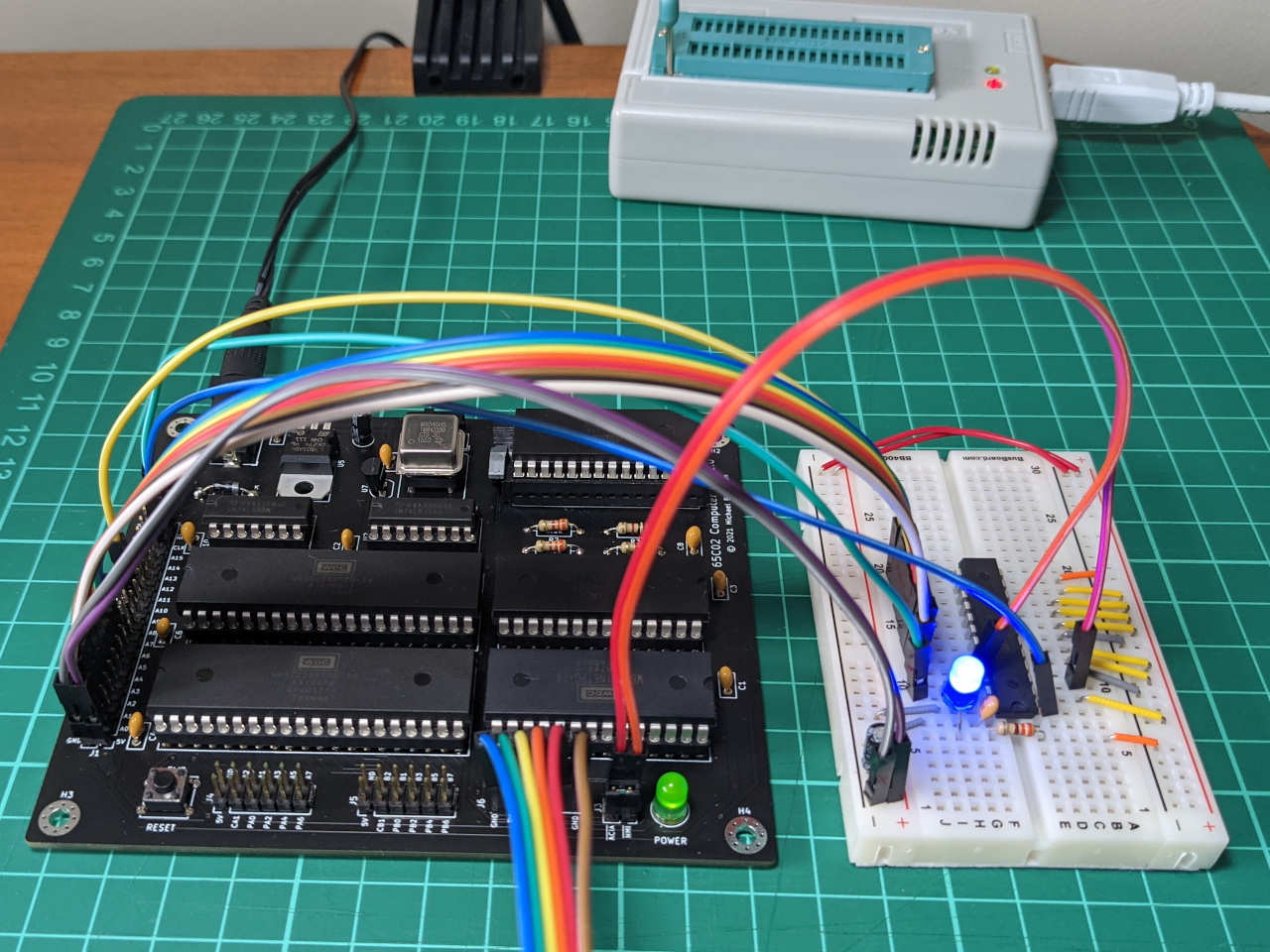
After testing everything on breadboard, I connected the new interrupt controller to my 6502 computer. All of the required signals are exposed via pin headers on my 6502 computer, more information about that can be found on previous blog posts.
This is how it looks. It’s not the neatest, but at least I don’t have the whole computer on breadboards anymore.
I then started writing some 6502 assembly code to test this out. I’ve been working on a shell which runs named commands, so I added a command called irqtest. This code references other parts of the ROM, which can be found in the GitHub repository for this project.
This code sets up a timer to trigger an interrupt on the 65C22 VIA, then uses the wai instruction to wait for interrupts. When the interrupt service routine completes, the code resumes. I’ve assigned two addresses (DEBUG_LAST_INTERRUPT_INDEX and DEBUG_INTERRUPT_COUNT) so that we can check that the correct interrupt routines are running.
; Set up a timer to trigger an IRQ
IRQ_CONTROLLER = $8C00

; Some values to help us debug
DEBUG_LAST_INTERRUPT_INDEX = $00
DEBUG_INTERRUPT_COUNT = $01

shell_irqtest_main:
  lda #$ff              ; set interrupt index to dummy value (so we can see if it's not being overridden)
  sta DEBUG_LAST_INTERRUPT_INDEX
  lda #$00              ; reset interrupt counter
  sta $01
  ; setup for via
  lda #%00000000        ; set ACR. first two bits = 00 is one-shot for T1
  sta VIA_ACR
  lda #%11000000        ; enable VIA interrupt for T1
  sta VIA_IER
  sei                   ; enable IRQ at CPU - normally off in this code
  ; set up a timer at ~65535 clock pulses.
  lda #$ff              ; set T1 low-order counter
  sta VIA_T1C_L
  lda #$ff              ; set T1 high-order counter
  sta VIA_T1C_H
  wai                   ; wait for interrupt
  ; reset for via
  cli                   ; disable IRQ at CPU - normally off in this code
  lda #%01000000        ; disable VIA interrupt for T1
  ; Print out which interrupt was used, should be 02 if irq1_isr ran
  lda DEBUG_LAST_INTERRUPT_INDEX
  jsr hex_print_byte
  jsr shell_newline
  ; print number of times interrupt ran, should be 01 if it only ran once
  lda DEBUG_INTERRUPT_COUNT
  jsr hex_print_byte
  jsr shell_newline
  lda #0
  jmp sys_exit
I set my interrupt service routine read from the interrupt controller, then jump to the correct routine.
irq:
  phx                       ; push x for later
  inc DEBUG_INTERRUPT_COUNT ; count how many times this runs..
  ldx IRQ_CONTROLLER        ; read interrupt controller to find highest-priority interrupt to service
  jmp (isr_jump_table, X)   ; jump to matching service routine

irq_return:
  plx                       ; restore x
  rti
The interrupt controller can return 11 possible values, so I made an 11-entry table, with the address for each interrupt handler (2 bytes each). I have connected the VIA to IRQ1, so I set the second entry to a subroutine called irq1_isr.
isr_jump_table:              ; 10 possible interrupt sources
.word nop_isr
.word irq1_isr
.word nop_isr
.word nop_isr
.word nop_isr
.word nop_isr
.word nop_isr
.word nop_isr
.word nop_isr
.word nop_isr
.word nop_isr               ; 11th option for when no source is triggering the interrupt (phantom interrupt)
Most of the interrupt routines map to nothing at all. If this were a real OS, an interrupt from an unknown source would need to be a fatal error, since it can’t be individually masked/ignored on this hardware.
nop_isr:                         ; interrupt routine for anything else
  stx DEBUG_LAST_INTERRUPT_INDEX ; store interrupt index for debugging
  jmp irq_return
When IRQ1 is triggered though, this routine will clear the interrupt on the VIA. If we fail to do this, then the CPU will become stuck, processing interrupts forever.
irq1_isr:                        ; interrupt routine for VIA
  stx DEBUG_LAST_INTERRUPT_INDEX ; store interrupt index for debugging
  ldx VIA_T1C_L                  ; clear IFR bit 6 on VIA (side-effect of reading T1 low-order counter)
  jmp irq_return
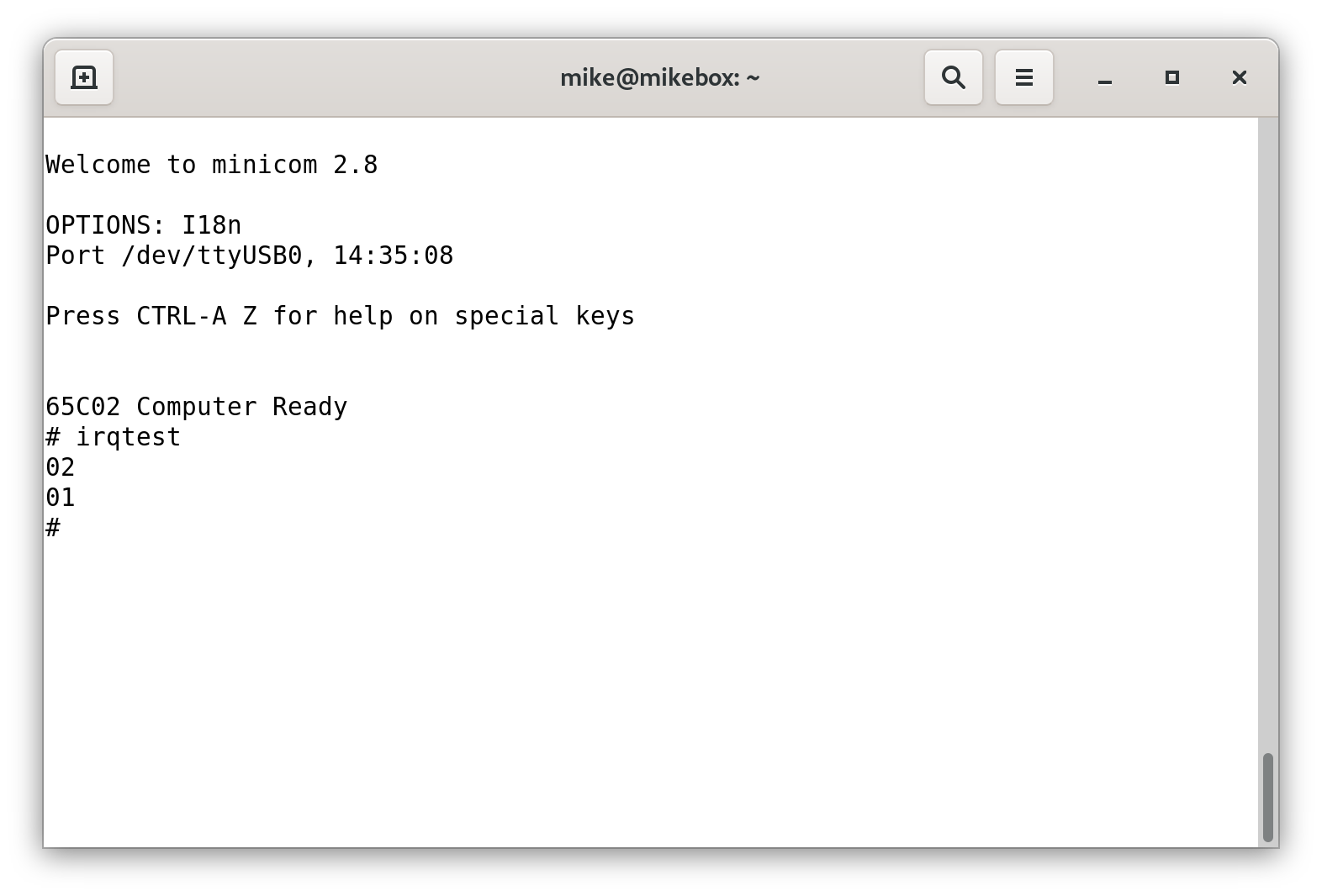
Once I fixed some bugs, I was able to get the expected output, which is 02 (the index we are using to jump into isr_jump_table), followed by 01 (the number of times the interrupt service routine runs).
While I was researching this, I also found that online 6502 assembly guides often suggest clearing the interrupt flag on I/O chips near the start of the interrupt service routine, apparently to avoid running the routine twice. From this test, I know that the interrupt service routine is only running once, so I am happily disregarding that advice. Thinking about it, I can only see this applying to open-drain IRQ outputs.
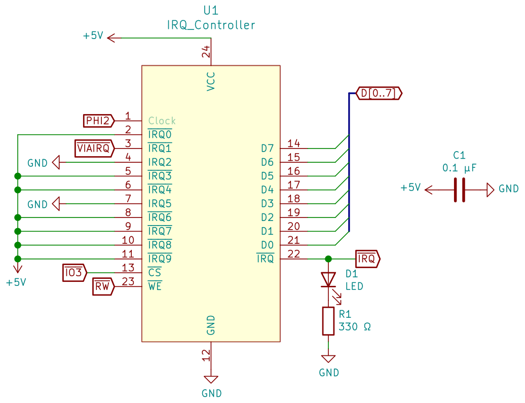
Note about KiCad symbols
Since my last blog post about PLD’s, I’ve started to create separate symbols in KiCad for each programmed chip. You can see one of these in the schematic above.
I’m producing these automatically. Galette has a .pin file as one of its outputs. The file for this chip is as follows:
 Pin # | Name     | Pin Type
-----------------------------
   1   | Clock    | Clock/Input
   2   | /IRQ0    | Input
   3   | /IRQ1    | Input
   4   | IRQ2     | Input
   5   | /IRQ3    | Input
   6   | /IRQ4    | Input
   7   | IRQ5     | Input
   8   | /IRQ6    | Input
   9   | /IRQ7    | Input
  10   | /IRQ8    | Input
  11   | /IRQ9    | Input
  12   | GND      | GND
  13   | /CS      | Input
  14   | D7       | Output
  15   | D6       | Output
  16   | D5       | Output
  17   | D4       | Output
  18   | D3       | Output
  19   | D2       | Output
  20   | D1       | Output
  21   | D0       | Output
  22   | /IRQ     | Output
  23   | /WE      | Input
  24   | VCC      | VCC
To produce schematic symbols, I wrote a small Python script to convert this text format to a CSV file, suitable for KiPart.
IRQ_Controller

Pin,Type,Name
1,input,Clock
2,input,~IRQ0
3,input,~IRQ1
4,input,IRQ2
5,input,~IRQ3
6,input,~IRQ4
7,input,IRQ5
8,input,~IRQ6
9,input,~IRQ7
10,input,~IRQ8
11,input,~IRQ9
12,power_in,GND
13,input,~CS
14,output,D7
15,output,D6
16,output,D5
17,output,D4
18,output,D3
19,output,D2
20,output,D1
21,output,D0
22,output,~IRQ
23,input,~WE
24,power_in,VCC
KiPart ships with profiles for FPGA chips, but the generic input worked fine for the ATF22V10 PLD.
./KiPart/venv/bin/kipart -r generic --overwrite irq_controller.csv
The output is a .lib file, which I can include in any KiCad project.
Wrap-up
This approach works, and introduces far less overhead compared with checking each device in the interrupt service routine. In particular, it will allow me to test interrupts from slow-to-access SPI devices.
I will be disconnecting this this for now, but may include it in an expansion board or updated computer design if I ever make one!