I recently attempted to add SD card support to my home-built 6502 computer.
This was successful, but more challenging than I expected. This blog post is just a few things that I learned along the way.
Background
SD cards are a popular way to add storage to electronics projects. In my case, I will be using the SD card in SPI mode. My home-built computer has an expansion port with some GPIO pins, which should be sufficient for this.
My basic plan was to:
- write some test data to an SD card from a modern computer
- interface the SD card to my home-built 6502 computer
- write a 6502 assembly program to print out the test data
Since this is a learning project, I started from scratch, and avoided reading any existing implementations of SPI or SD cards before jumping in.
Test data
I started this project by generating a small test file, repeating each character in the alphabet 512 times.
echo abcdefghijklmnopqrstuvwxyz | fold -w1 | while read line; do yes $line | head -n512 ; done | tr -d "\n" > disk.img
It takes a one-line shell command to write this image to an SD card on all good operating systems, or a few clicks in the disk imaging utility.
dd if=disk.img of=/dev/my_sd_card
My laptop has an SD card slot, but I also have Windows on it at the moment, which turned this into a far larger problem than I could have imagined.
Driver support for this particular SD card reader was dropped in Windows 10, there are no built-in tools for imaging disks on Windows, and I had to try multiple tools before I could find one which would write a raw disk image (one which does not contain a valid filesystem).
In retrospect, this was the first of many lessons about not having the right tools for this project.
Physical interface
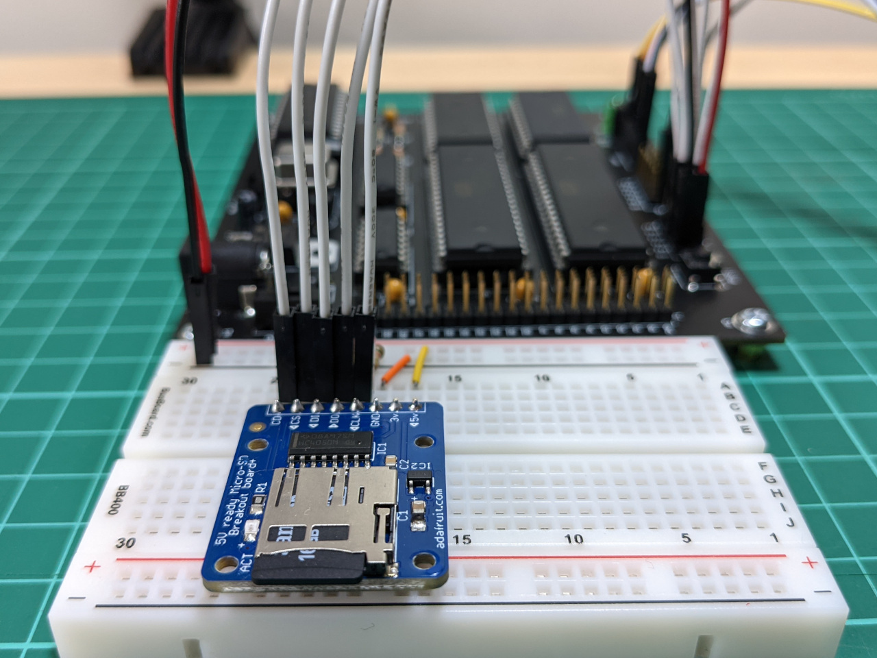
I connected an SD card module to my 6502 computer, via a breadboard. I used a module which could level-shift, because my computer runs at 5V, where SD cards usually run at 3.3V. This particular module is an Adafruit ADA254.
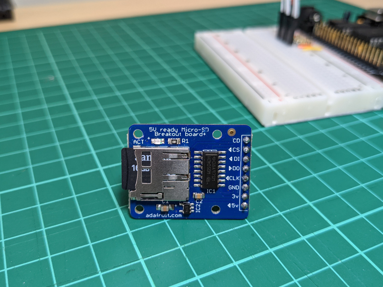
I also added pull-up resistors to all of the data lines, after noticing that there were several sitations where they would float. The wiring I used is:
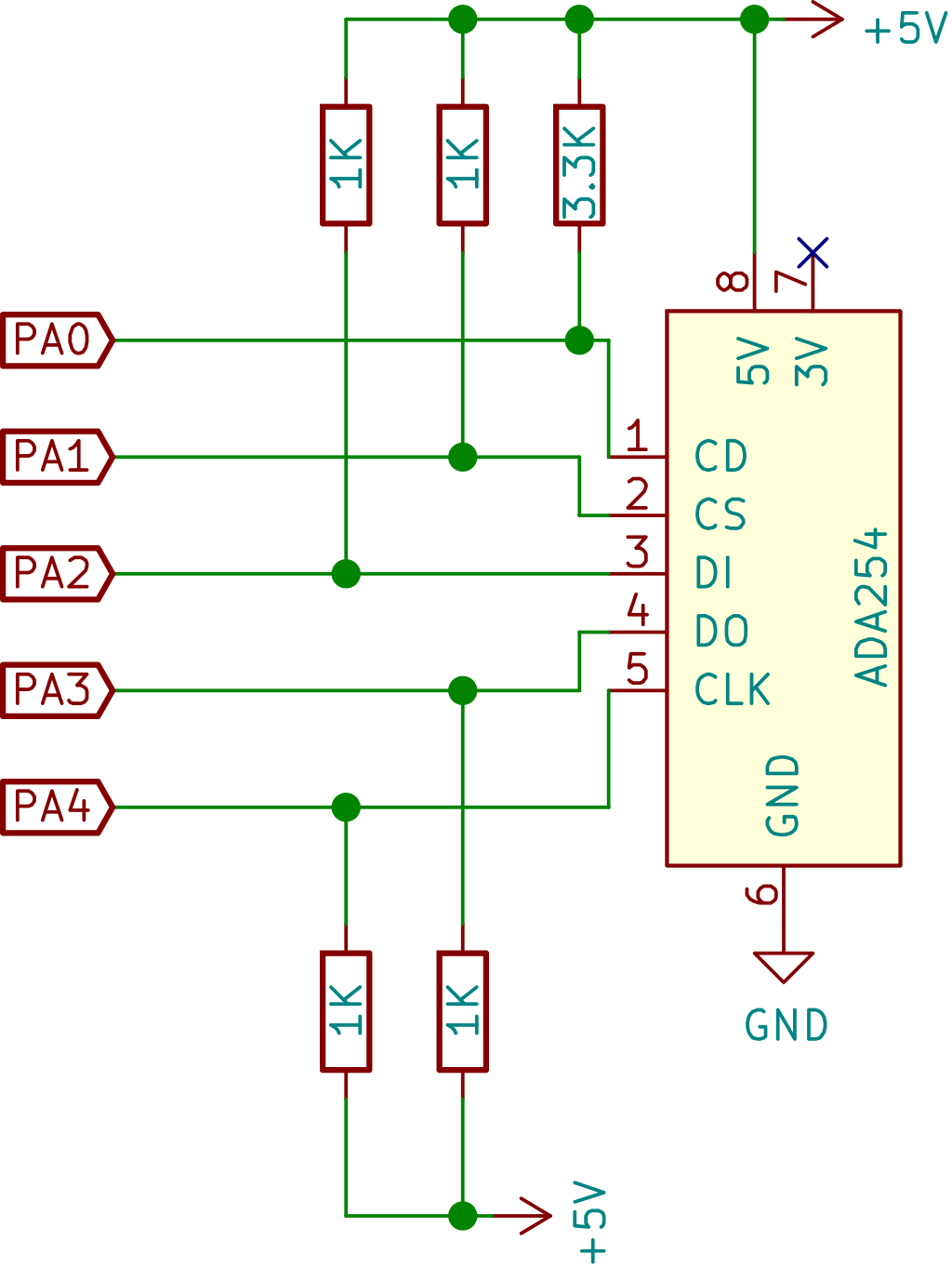
The full schematic for my 6502 computer is on this blog post, while the schematic for the SD card module is online here.
Software: Part 1
With some test data and a hardware interface, I got to the third step, which was to read data from the SD card. I was completely unprepared for how tricky it is to do this from scratch, without the right experience or debugging tools.
As a quick re-cap, my development environment is still very limited: I am writing 6502 assembly on a modern computer, and I have the ability to send the assembled program to my home-built 6502 computer over a serial connection.
I started by using lecture notes from the University at Buffalo’s EE-379 course, available online here. This describes SPI, SD card command structure, and the sequence to initialise a card.
The two protocols I needed to implement are SPI, which transfers the bits, plus the SD card commands which run over that. I had to write quite a lot of code with no feedback, because it takes several commands before SD cards are ready to work with in SPI mode, and the exact details vary depending on the generation of card (SDHC vs SDXC, etc).
After days of debugging, I was unable to get a response from the SD card. With few other options, I started filling my code with the assembly-language equivalent of print statements, and found that every byte from the SD card was the default FF. This means ’no data’ in this context.
Print statements also slowed the program down to a crawl, which allowed me to use a pizeo buzzer to listen to each line. This clicks each time a signal changes between 0 and 1, so I was able to check that each line had the expected activity. I found that the SD card was sending responses, but that the computer was not receiving them, because they were not connected to eachother on the breadboard.
Software: Part 2
After connecting the card correctly, I could see responses for the first time. The format here is byte sent / byte received, with line breaks between commands.
#
SD card detected
40/7f 00/ff 00/ff 00/ff 00/ff 95/ff ff/ff ff/01 ff/ff
48/7f 00/ff 00/ff 01/ff aa/ff 0f/ff ff/ff ff/09 ff/ff ff/ff ff/ff ff/ff
7a/7f 00/ff 00/ff 00/ff 00/ff 75/ff ff/ff ff/01 ff/00 ff/ff ff/80 ff/00 ff/ff ff/ff
#
The correct initialisation sequence depends on the type of SD card, and I spent a lot of time going through each possibility, looking for one one which worked. When this failed, I found this summary online, which includes more information about decoding the responses: Secure Digital (SD) Card Spec and Info.
As it turned out, I was not sending the correct CRC for CMD8, and a CRC error is indicated by the 09 (binary 0000 1001) response to the second command above. Each bit in the response has a different meaning, and I had mistaken this for indicating an unsupported command, which is expected for some card types.
It’s a good thing that I had this problem, because searching for the CRC algorithm turned up this collection of AVR C tutorials, which includes a 4-part series on implementing SD card support.
I noticed that all of the command examples were wrapped with code like this:
    // assert chip select
    SPI_transfer(0xFF);
    CS_ENABLE();
    SPI_transfer(0xFF);
    // ... code to send a command...
    // deassert chip select
    SPI_transfer(0xFF);
    CS_DISABLE();
    SPI_transfer(0xFF);
Later on, I had a problem where responses were sometimes mis-aligned by one bit. When I also tried sending empty bytes between commands, while the SD card is not selected, these problems disappeared entirely.
Software: Part 3
With the initialisation code complete, I could finally request data from the SD card.
Data on an SD card is arranged in 512-byte blocks by default. I wrote a routine to read one block of data from the SD card into RAM, plus a routine to print sections of RAM.
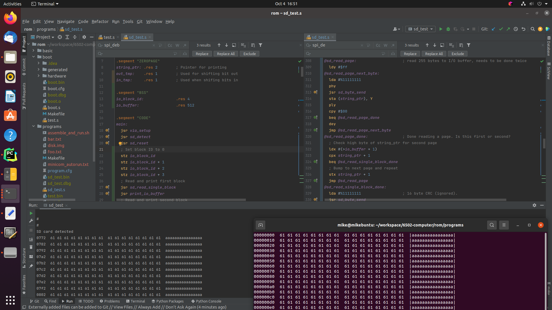
The result was a program which prints the first kilobyte of the SD card, which is the letter a 512 times, followed by the letter b 512 times.
This screen capture shows the output of a program matching a hexdump of the test file, which is exactly what I was aiming for.
The full code is too long to include in a blog post, but can be found in the repository for this project, mike42/6502-computer on GitHub.
Some lessons
While I was able to read data from an SD card, this took a long time, and there were several points where I nearly hit a dead-end.
I couldn’t see what was happening at a hardware level, and I couldn’t compare my setup with one that worked, because I had never done anything similar before. Spot-the-difference is a powerful debugging tool, and by jumping straight into 6502 assembly, while avoiding existing 6502 implementations, I definitely made things difficult for myself.
With that in mind, there are several ways I could have made this easier:
- Better equipment. A logic analyser, an SD card writer, and spare SD cards would have been useful for testing.
- Building somewhere less-constrained first. I could have implemented this first on a Raspberry Pi, then ported the result to 6502 assembly. It would then be possible to verify my hardware setup by running existing code, while still getting the learning experience from writing my implementation from scratch. Note that this would have required a different SD card break-out board.
- Building something simpler first. For example, Ben Eater released a a YouTube video around the time I was working on this, where he reads from an SPI temperature sensor on a 6502 computer. It would be much easier to get started if I had used any other SPI device on a 6502 first.
The next step in this project is to load programs from an SD card, which would require me to implement a filesystem. This is significantly more complex than what I’ve done here, and I know not to approach it the same way.
More equipment
I picked up a logic analyser, USB SD card reader, alternative SD card module, and a spare SD card.
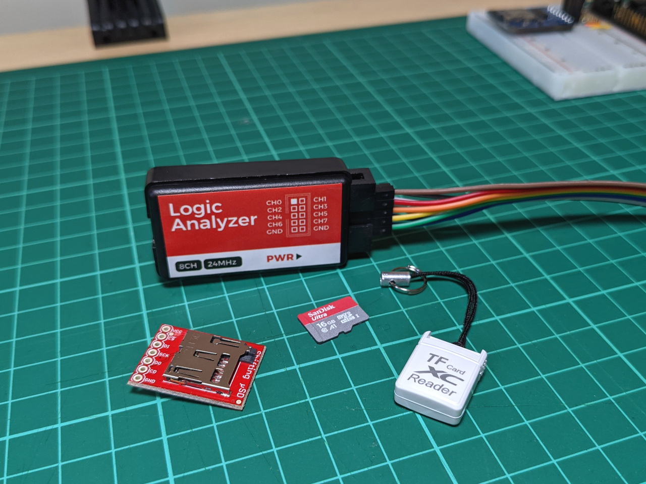
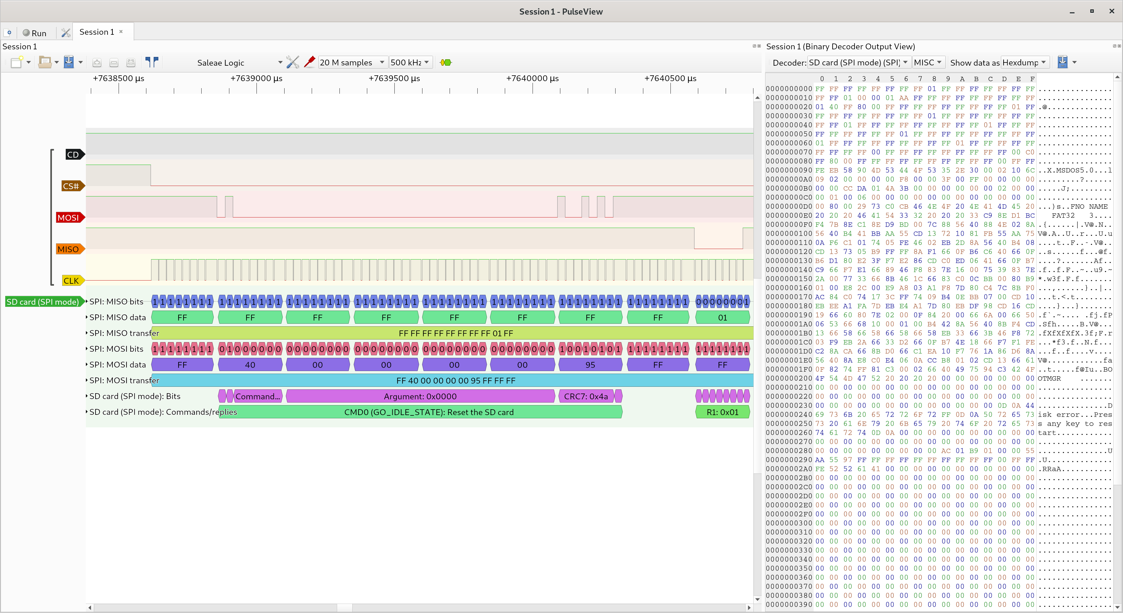
The logic analyser is compatible with sigrok, which is open source. This is the first time I’ve used this software, and it can decode SD card commands running over SPI, among other things.
The USB SD card reader will allow me to write disk images directly from my development environment, instead of copying them over to a laptop. I do most of my development from a virtual machine, and USB peripherals are easy to pass though.
The alternative SD card module is from SparkFun. Compared with the module I was using in this blog post, it has a smaller footprint, and includes the pull-up resistors. I’m hoping I can use this to fit an SD card into the 3D-printed enclosure for this project.