I recently built a computer from scratch, and wanted to add some basic sound output. I am not attempting to produce any 8-bit music, but I would like to be able to write programs use beeps and clicks to provide feedback, instead of only text.
I did a bit of digging into the subject, and found quite possibly the world’s worst sound card, in the Apple II. This is my attempt to re-draw the relevant part of the schematic, which I found in a 1983 publication called The Apple II Circuit Description.
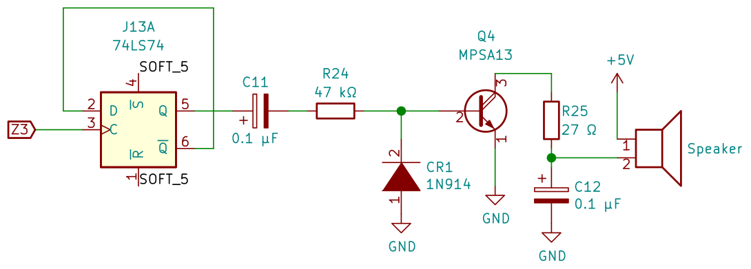
The linked book does a good job of explaining the details, but the important part for this blog post is simply that Z3 is an address decoding output. It is normally high, but is low for half a cycle each time that memory address $C030 is accessed. This is fed to a flip-flop, which will toggle each time this happens, driving a speaker.
This should be easy for me to implement, since I have spare address decoding outputs on my computer.
First attempt
I decided to use a piezo buzzer, which can be driven directly from an IC pin, simplifying things greatly.
I first connected the buzzer directly to one of the spare address decoding outputs of my computer.
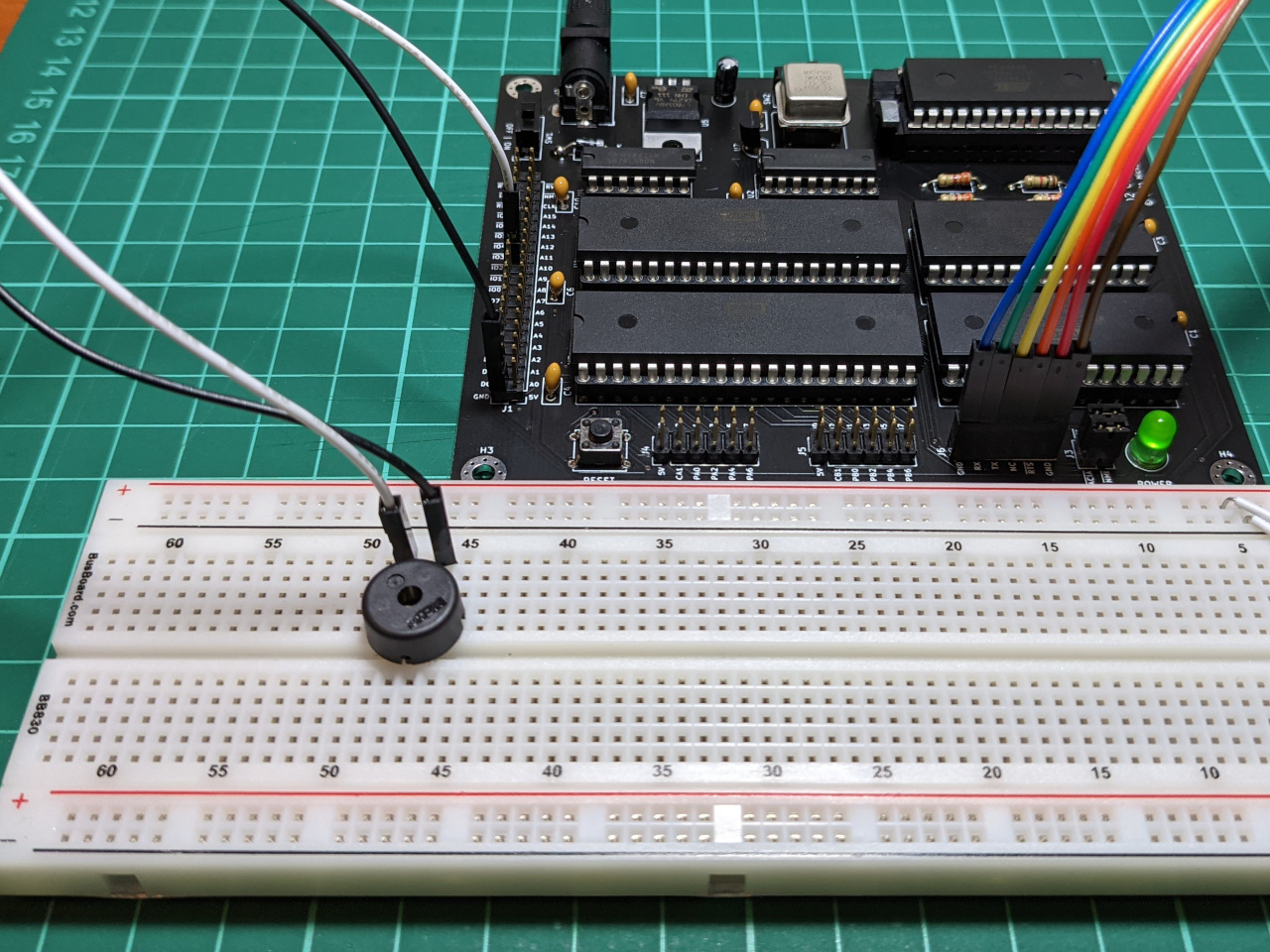
This is so simple that it is almost not worth diagramming, but here goes:
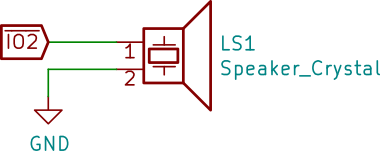
The input is IO2, which works out to address $8800 in my computer’s memory map. I wrote a bit about in an earlier blog post.
From BASIC (yes, this computer runs BASIC), I can read from this address and produce a click.
A=PEEK($8800)
Second attempt
To produce a beep, I wanted a square wave with a 50% duty cycle. The Apple II used a 74LS74 dual D flip flop IC for this, which I don’t have in my inventory. Instead, I used a 74AC163 4-bit counter.
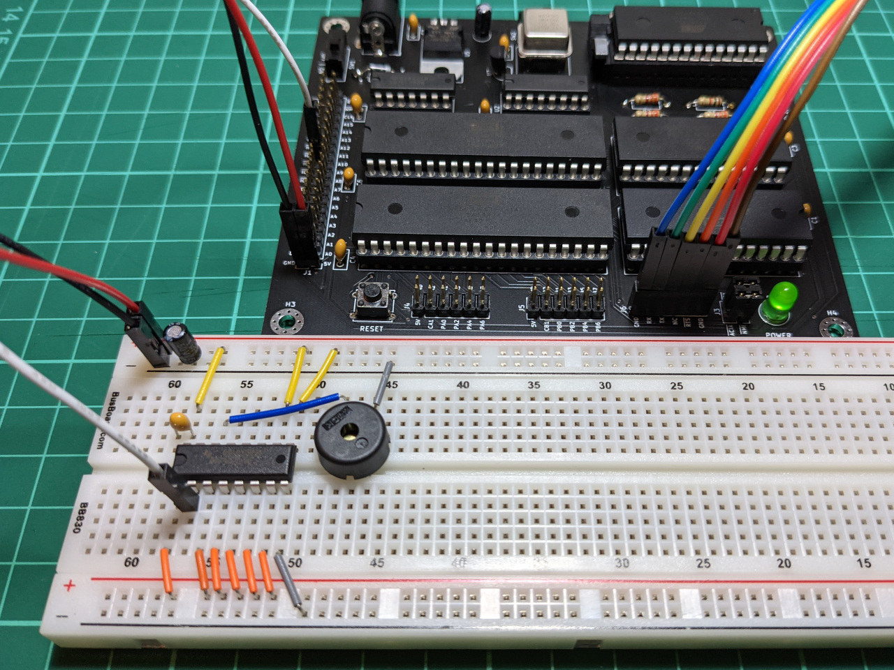
The circuit on the breadboard is wired up like this:
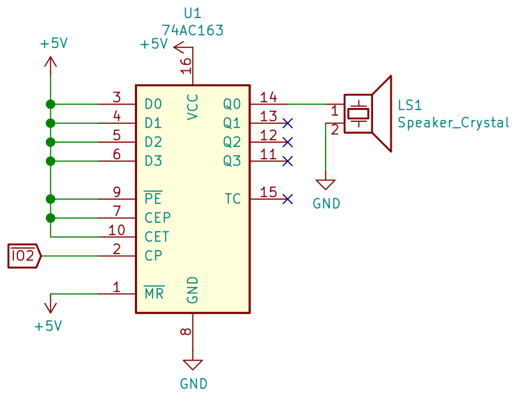
I was then able to produce a beeping sound by reading a memory address in a loop, just as you could on the Apple II.
10 A=PEEK($8800)
20 GOTO 10
RUN
Mission accomplished.
Alternatives and next steps
I’ve already started adding clicks and beeps to assembly code while testing, and my immediate plan is to add a separate startup beep for each of the two boot ROMs. If I ever do a second revision of this computer board, I’ll most likely add a speaker as an on-board peripheral, using a 74LS74 instead of the counter.
There are two other methods which considered for adding beeps to this computer. The first was to utilise its 65C22 chip, which can be set to output a square wave on its PB7 pin. I have other plans for that output, which is the reason I haven’t used it for sound.
The second idea I looked into was sampled audio, which would require me to latch 8-bit audio samples a few thousand times per second, and then use some resistors to build a digital-to-analog converter. There are a few ways that I could achieve this with parts which I have on-hand, such as a SN74AC573 latch, or the 65C22.