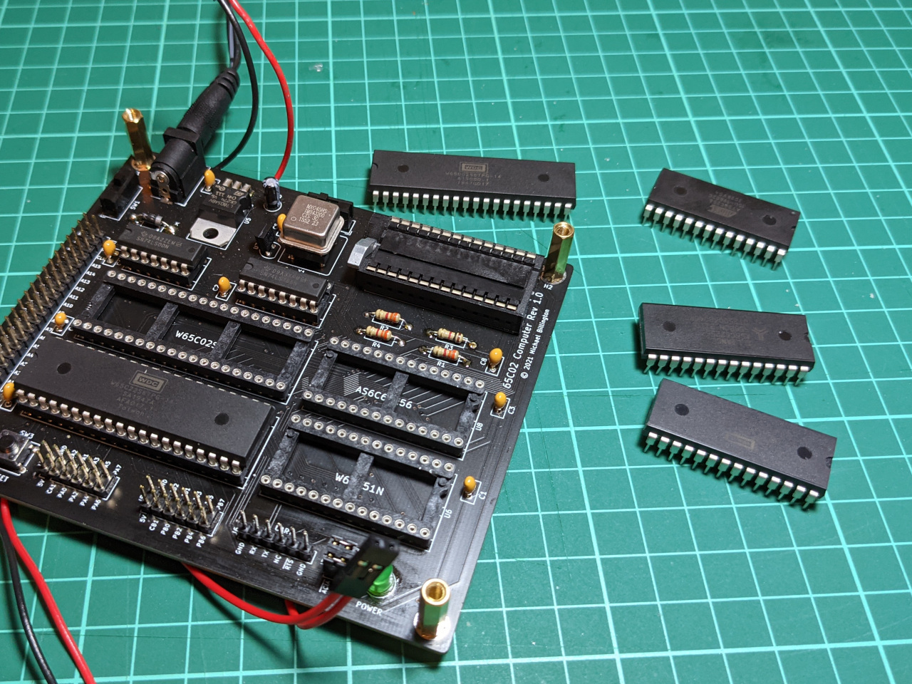
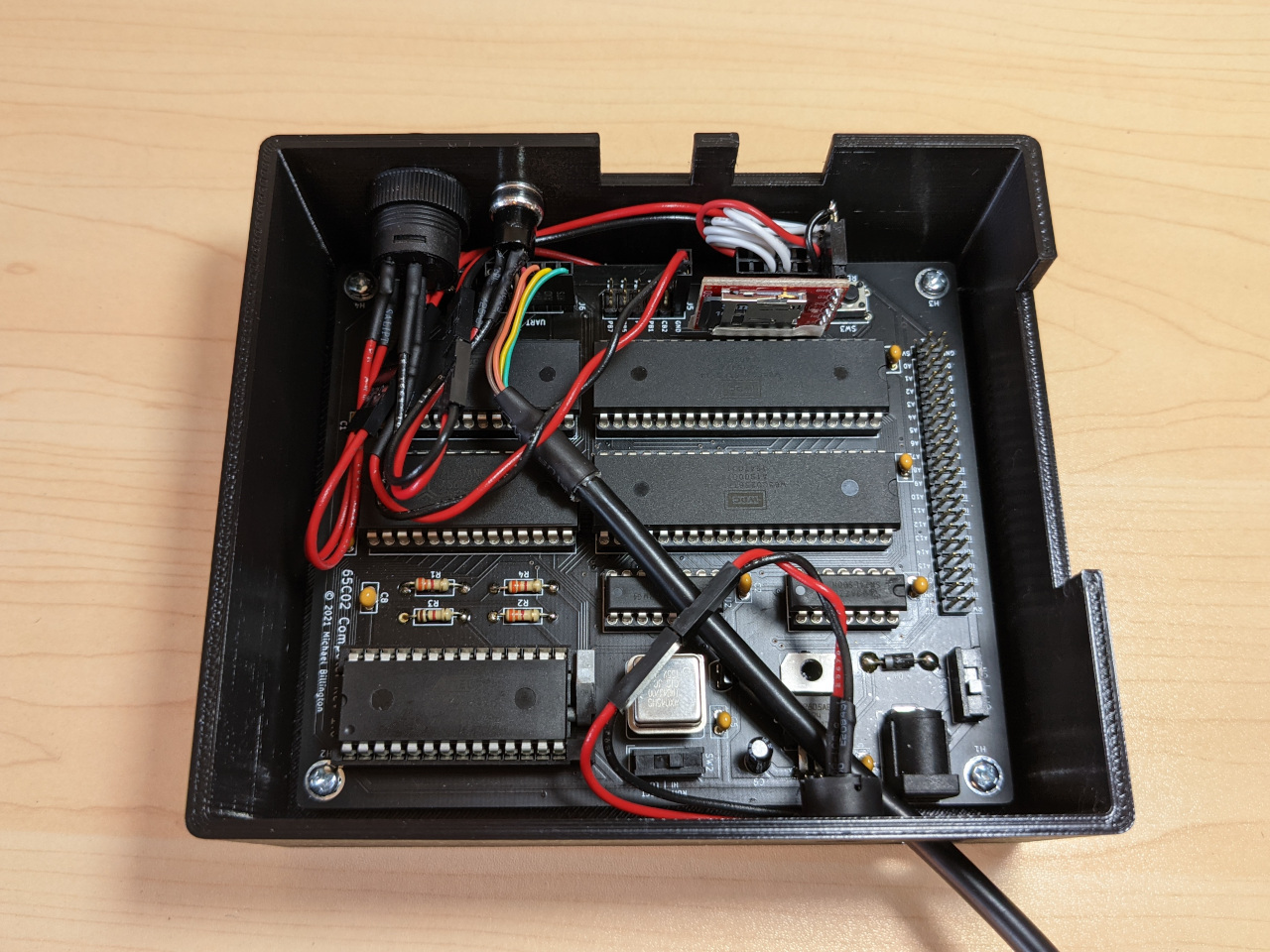
I recently finished assembling my 6502 computer, so that the whole project is housed in a 3D-printed case.
This is something that should be easy. I already blogged about making the case, and making the circuit board. All that is left is to put the board in the case, right? Well thanks to some mistakes on my part, things are not quite so simple.
More parts
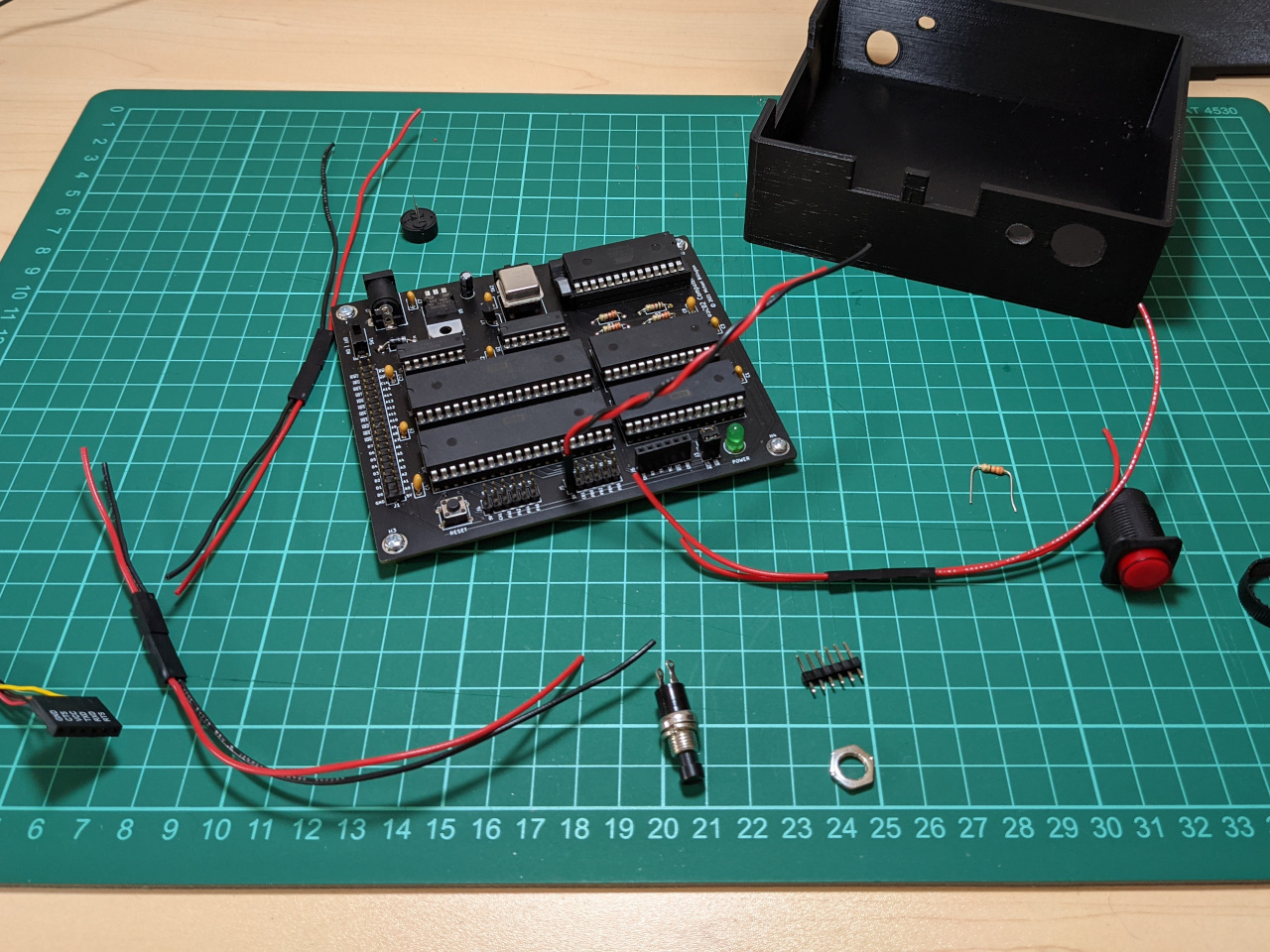
I needed quite a few parts to finish this project, including a power button, reset button, hex standoffs, short screws, and rubber feet. Since this is the first time I’m hitting this stage of a project, I also needed to buy a Du Pont connector kit, stranded wire, heat-shrink tube, and glue.
I have been powering the project from a USB/serial adapter, so I also bought a new one to install permanently. A full parts list is available in the GitHub repository for this project.
I also needed to widen the hole for the reset button due to a mix-up. The specific part I used requires a 7mm hole, while I had designed the case for a button with a 6mm hole.
Making connections
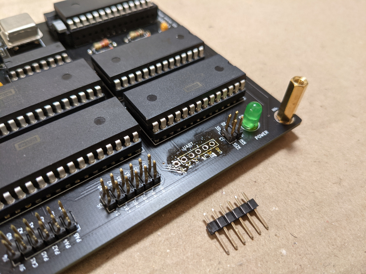
The first step was to modify the board so that it would be compatible with the new UART, which involved de-soldering the female pin headers which I installed previously, and replacing them with male pin headers. I used only a soldering iron, solder wick, and flux for de-soldering, and it was not a fun process. The board survived, so I’ll call it a success.
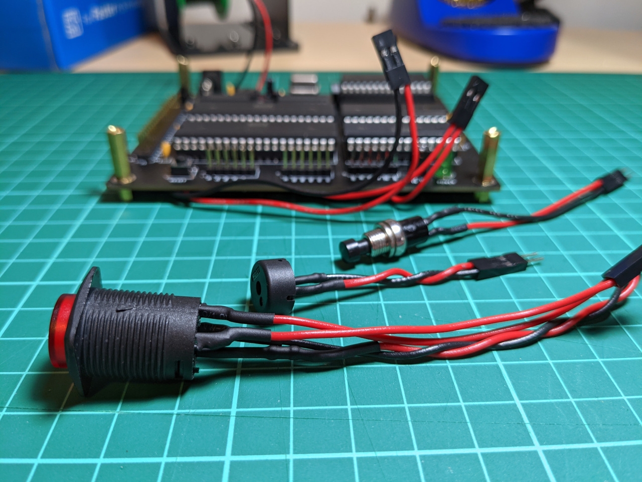
Next, I soldered wires to the underside of the board for the power button, reset button, and speaker to connect. Each of these is a pair of wires, soldered at one end, and a 2-pin female Du Pont connector on the other.
I attached corresponding connectors on the buttons and speaker. The power button also has an in-built LED, and there are plenty of places to power this from the board’s expansion headers. I added a 2-pin female Du Pont connector, plus a resistor, neatly hidden by heat-shrink.
I checked everything with a multimeter before powering it on. The UART pins were connected correctly to the 65C51N chip and ground. No continuity between the board’s power and the external power unless the power button is pressed, no continuity between the reset line and ground unless the reset button is pressed, and so on.
Troubleshooting
When I powered on the computer, nothing came up on the terminal, which means that I broke something. I tested some voltages, and found the computer was stuck in reset.
The reset signal on the 6502 is active-low, and I’ve added a supervisory IC. Any time the reset signal is low, or the power drops below a minimum voltage, this IC holds it low for 150ms before returning it to +5v. I was confident that the reset buttons and power voltage were fine, so I suspected that one one of the other chips could be causing the problem.
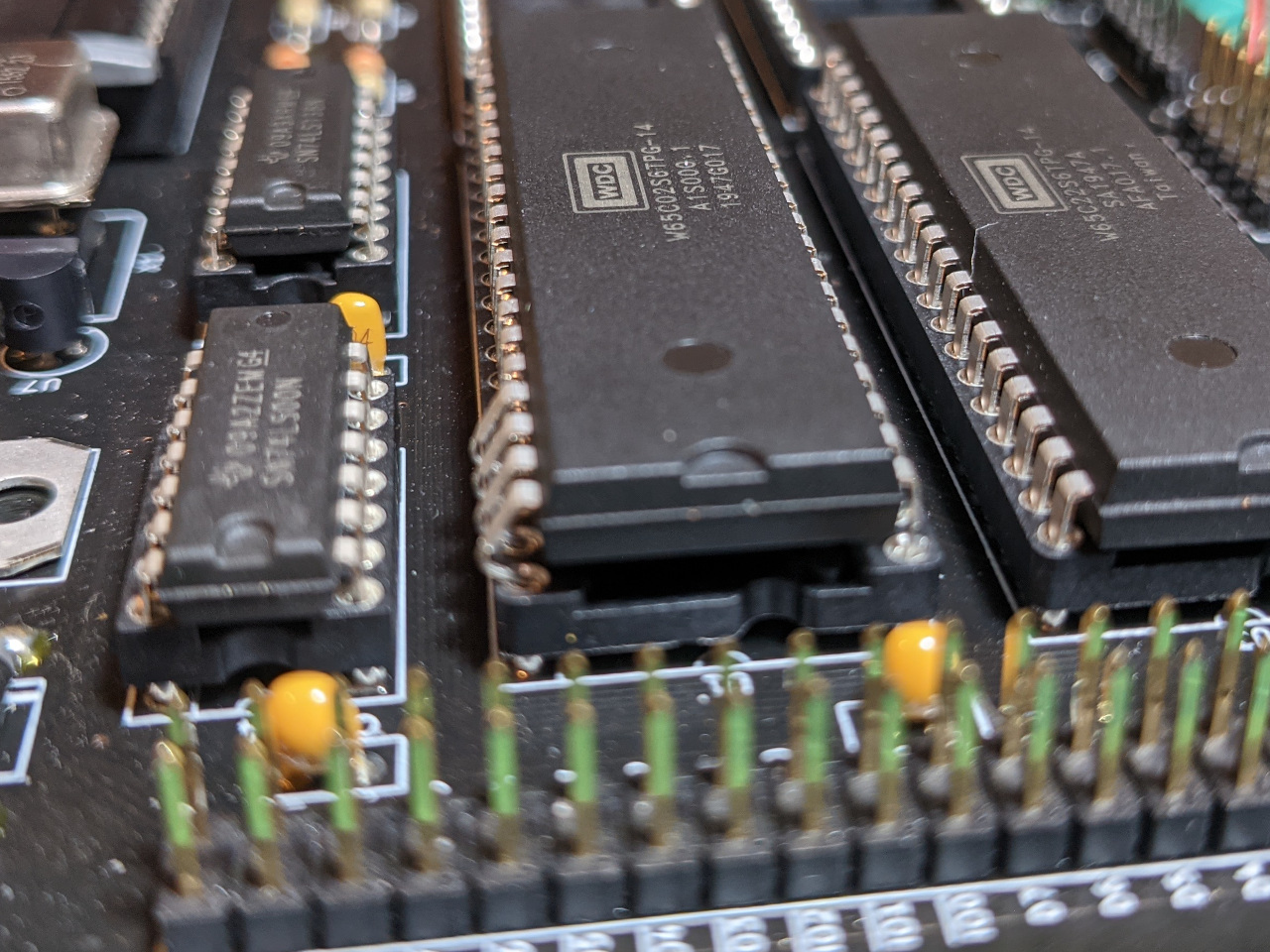
Everything is socketed, so I removed the 65C51N and tested again. This chip is closest to the de-soldering work I was doing earlier, so I thought I may have damaged it.
There was no change, so I started removing other chips, and found that after removing the CPU, the computer was no longer getting stuck in reset.
Following that lead, I found that one of the data bus lines, D4, was connected to the reset line. This would cause activity on the data bus to reset the computer, which would cause this problem.
A quick look at the board in KiCad showed that at one of the points I had attached the reset button, D4 is 0.5mm away from the reset line.
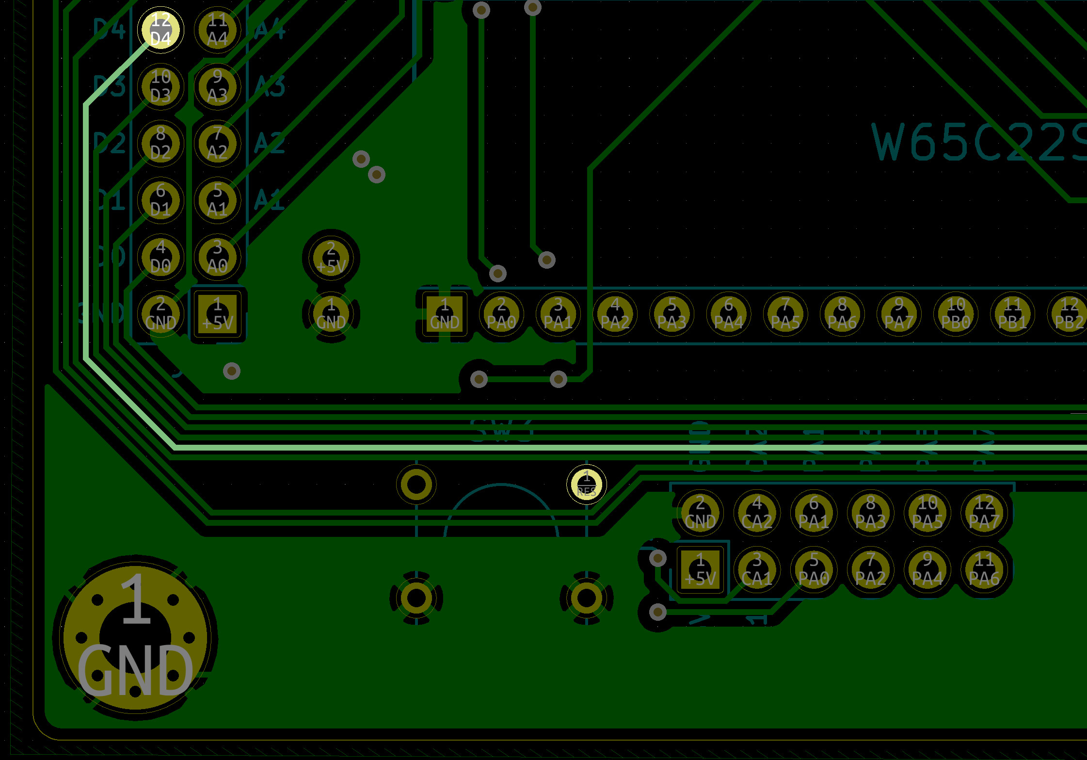
I de-soldered that wire and found a tiny break in the solder mask on D4. This was easy enough to fix, I simply attached the wire for the external reset button elsewhere.
I also bent the CPU pins when re-installing, but after fixing that, I was back in business.
SD card changes
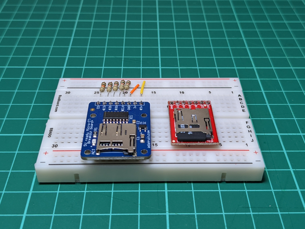
I have been writing some test programs which use a microSD card via one of the 65C22 I/O ports, and wanted to fit this in the case as well.
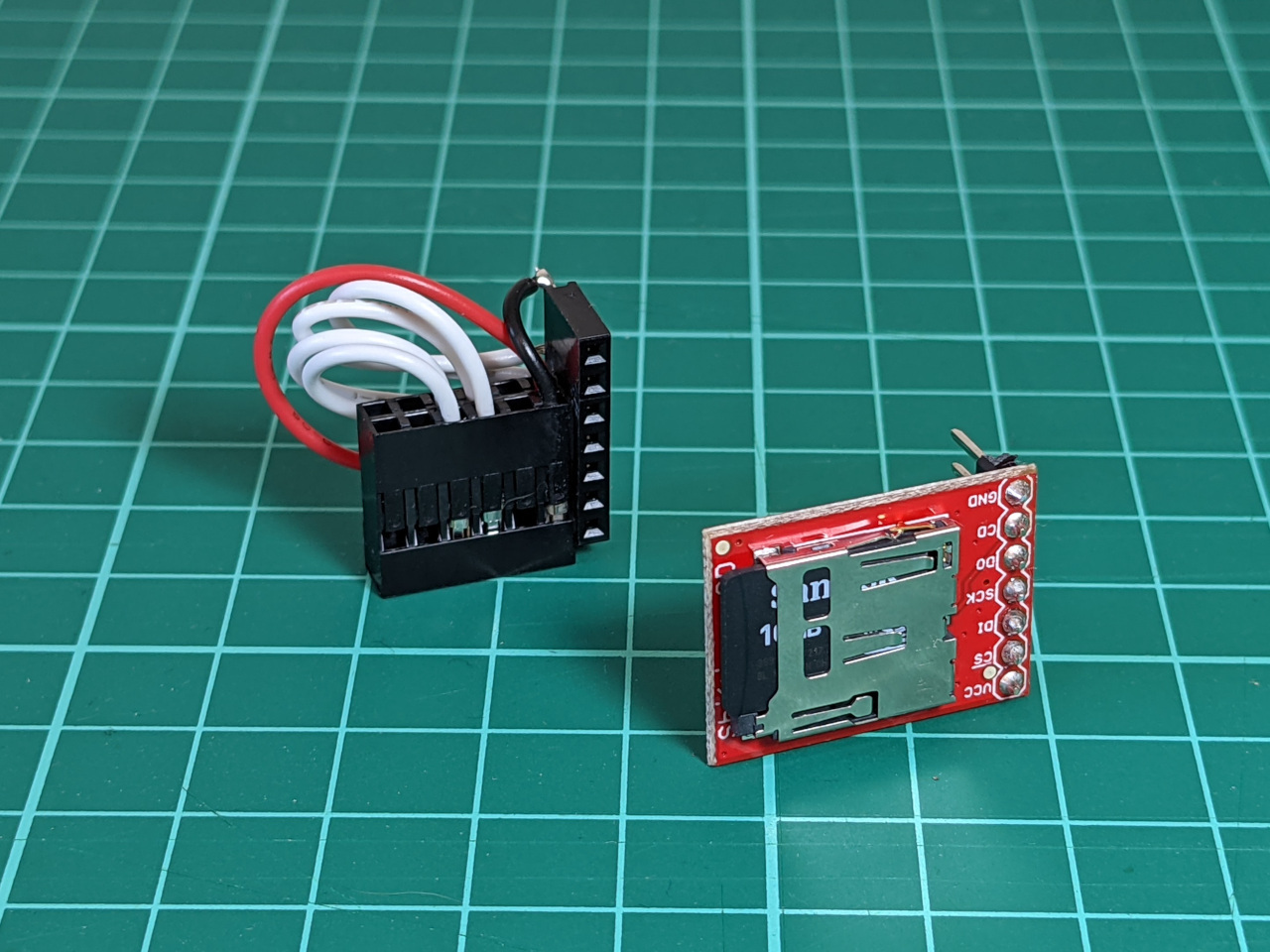
I swapped the Adafruit ADA254 microSD break-out for the SparkFun DEV-13743. It is slightly smaller, includes pull-up resistors, and still provides level-shifting.
I made a small adapter by attaching a female pin header to a Du Pont housing with superglue. I couldn’t get the “card detect” feature to work, so I wired it up differently to my previous blog post, and updated the code to match. Details of the new wiring is on GitHub.
I also added some masking tape when I installed this to prevent any short circuits. The metal on the outside of the microSD socket is connected to ground, and it could touch some IC pins.
Quick lessons
This is only a learning project for me, so I am trying to take some lessons away from each part of it.
The high-level lessons would be to plan for external connections before building the PCB, and to have all parts on hand before designing the case. That would have saved a lot of re-work, though adapting a design without starting from scratch is a valuable skill in itself.
If I were starting from scratch, I would add pin headers to the board for connecting the power and reset buttons instead of including buttons on the board, and remove the (now unused) DC barrel jack as a power input. I would also make the board larger, and the case taller, so that everything is less cramped. It takes a lot of force to remove chips from machined pin sockets, and the board is too compact to get a screwdriver under the chips.
SD card support is also a bit of a hack, and could be built-in to the board with some effort.
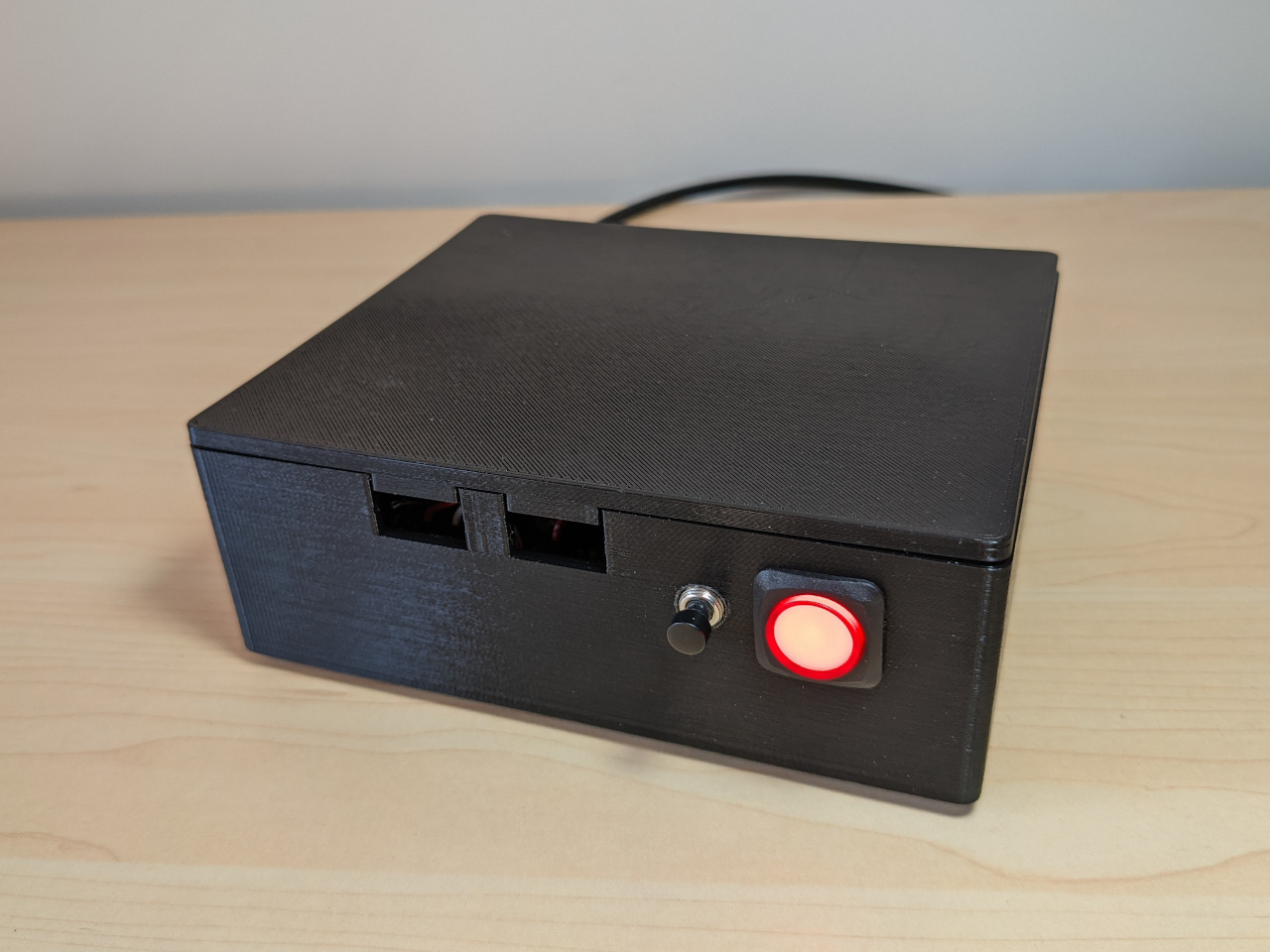
Final results
I now have a fully self-contained 8 bit computer, and it looks more like a finished project than an in-progress experiment. It boots to BASIC, or with the flip of a switch, launches a ROM which allows me to load machine code assembled on my PC.
With the lid removed, I can access the 40-pin expansion header, and one spare I/O port.
The hardware side of this project is now done, and I have a platform for testing any 6502 assembly code on real hardware.